In mechanical product development, robotics engineering, and advanced hardware prototyping, selecting the right manufacturing process during early-stage validation determines whether a project meets its design freeze schedule or suffers costly redesign cycles. When taking a 3D CAD model from digital concept to physical reality, engineering teams inevitably face the core prototyping dilemma: Subtractive CNC Machining vs. Additive Manufacturing (3D Printing).
The widespread adoption of industrial 3D printing technologies—Fused Deposition Modeling (FDM), Stereolithography (SLA), Selective Laser Sintering (SLS), and Direct Metal Laser Sintering (DMLS)—has popularized the idea that additive manufacturing is universally faster, cheaper, and more flexible for functional prototypes. However, production machine shop realities tell a more nuanced story. While 3D printing excels at unconstrained organic shapes, topology-optimized lightweighting, and early geometric fit-checks, subtractive CNC milling and turning remain indispensable whenever functional prototypes require true mechanical isotropy, precision bearing press-fits, airtight fluid sealing, or production-grade surface finishes.
Understanding the precise metallurgical, mechanical, and economic boundary where additive manufacturing reaches its physical limits—and where subtractive CNC machining becomes both mechanically superior and economically imperative—is an essential skill for engineering and procurement professionals.
At CNMP, our manufacturing engineering team routinely guides international hardware teams through this process selection matrix, providing on-demand rapid functional prototyping with turnaround times as fast as 3 to 5 business days and a strict MOQ = 1 piece policy.
To explore rapid subtractive prototyping workflows in depth, review our foundational guide on CNC prototyping services. For small-batch production transitions beyond initial validation, consult our resource on low-volume CNC machining.
1. The Core Mechanical Divide: Subtractive Cutting vs. Additive Sintering
To understand why CNC machined parts and 3D printed parts behave fundamentally differently under physical stress, engineers must first examine their raw material provenance and manufacturing physics.
| Metric / Feature | Subtractive CNC Machining | Additive 3D Printing (SLS/DMLS) |
|---|---|---|
| Raw Material Provenance | Continuous extruded or forged billets | Fused powders, resins, filament |
| Structural Homogeneity | 100% Fully dense, isotropic matrix | Micro-porous, layer-laminated |
| Achievable Tolerances | Down to ±0.005 mm (±0.0002 in) | Typical ±0.10 to ±0.30 mm |
| As-Produced Surface Finish | Ra 0.8 μm (down to Ra 0.4 μm) | Ra 6.3 to 12.5 μm (stair-step) |
| Airtight & Fluid Sealing | Inherently gas- and liquid-tight | Micro-capillary leaks common |
| Economic Crossover (Metal) | Cost-advantaged above 5–15 parts | Cost-advantaged for 1–3 parts |
The Physics of Subtractive CNC
Subtractive CNC machining begins with a solid billet, plate, or bar of wrought alloy or engineering thermoplastic. These raw stock billets are manufactured via continuous hot-rolling, forging, or extrusion, followed by standardized thermal treatments (such as T6 precipitation hardening for aluminum alloys or quench-and-temper for alloy steels).
Because the raw billet undergoes severe plastic deformation during metallurgical forming, its internal grain structure is densely compacted, continuous, and completely free of interior voids or trapped gas pockets. When rotary carbide cutters carve away unwanted stock on a 3-axis or 5-axis machining center, the resulting component retains the intact crystalline lattice of the parent billet.
The Physics of Additive Sintering
Additive manufacturing builds geometry from the ground up, depositing material in discrete two-dimensional slices that are thermally fused, cured, or laser-sintered layer upon layer.
Whether using photopolymerization (SLA), powder bed fusion (SLS/DMLS), or thermal extrusion (FDM), every additive process relies on molecular diffusion or thermal re-melting across an interface boundary. The material properties of the finished component are not dictated solely by the raw polymer pellet or metal powder chemistry; they are heavily influenced by the laser scan speed, melt pool overlap, chamber oxygen concentration, and cooling thermal gradients.
Material Certification & Regulatory Realities
In mission-critical hardware—such as aerospace flight controls, medical surgical instruments, or automotive fluid circuits—regulatory compliance mandates documented traceability to mill test certificates (EN 10204 Type 3.1).
Wrought CNC materials like 6061-T6, 7075-T651, 304/316L stainless steel, and medical-grade PEEK carry decades of standardized metallurgical performance data. Conversely, 3D printed polymers and laser-melted metal alloys often present batch-to-batch density variances, making regulatory approval during early clinical or flight qualification significantly more arduous.
2. Mechanical Strength & Material Isotropy: The Z-Axis Delamination Risk
The most significant engineering pitfall in functional prototyping is the assumption that a 3D printed component possesses the same structural strength as a CNC machined component of the same nominal material designation. In reality, additive parts are structurally anisotropic, while CNC machined parts are isotropic.
Isotropic vs. Anisotropic Physics
An isotropic material displays identical mechanical properties—such as tensile yield strength, modulus of elasticity, and shear resistance—regardless of the spatial axis along which stress is applied:
Isotropic Uniformity:
Stress_X = Stress_Y = Stress_Z
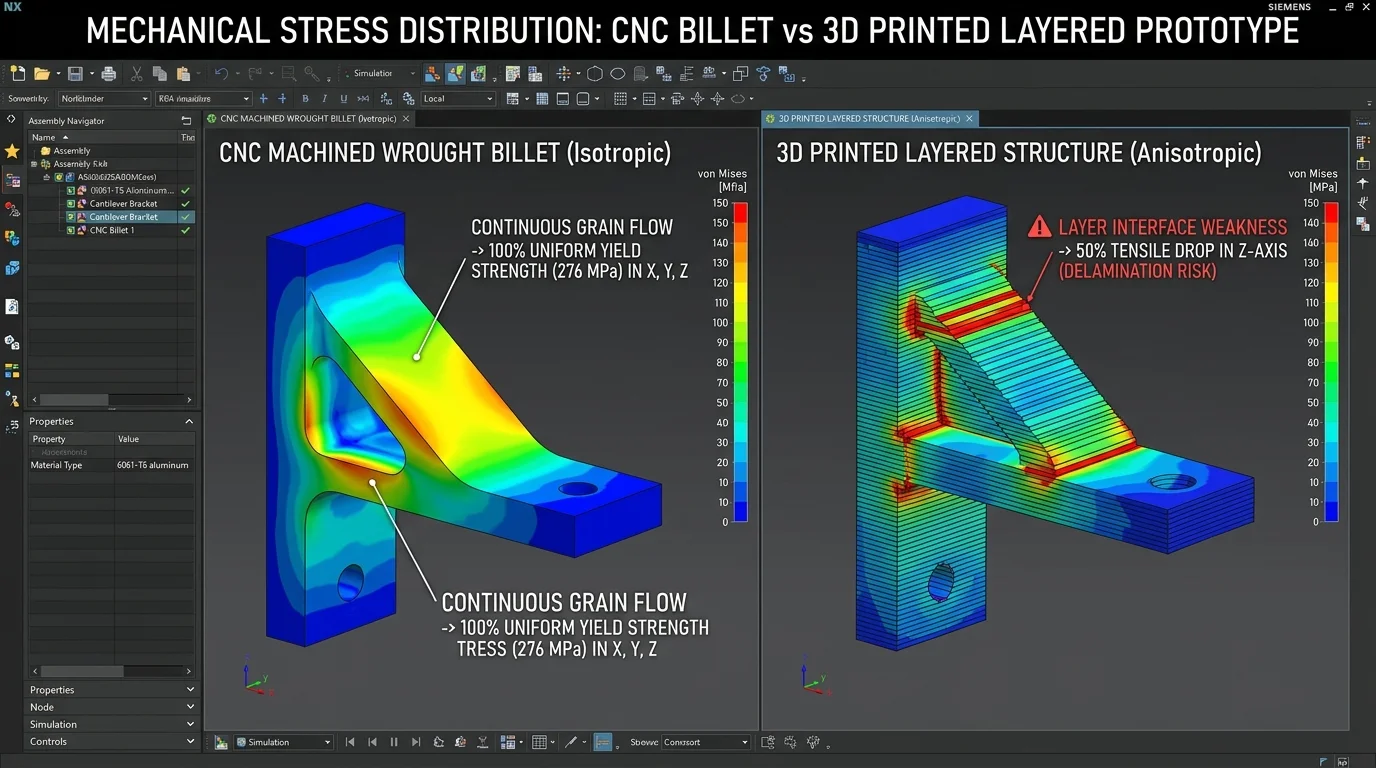
When an engineer machines a structural bracket from a 6061-T651 wrought plate, the part delivers a uniform tensile yield strength of 276 MPa whether tension is applied along the length, width, or thickness of the bracket.
In contrast, 3D printed parts exhibit pronounced anisotropy. Tensile strength in the horizontal build plane (X-Y axes), where polymer strands or sintered metal tracks are continuous, is significantly higher than in the vertical build direction (Z-axis). In the Z-axis, tensile loads act directly across the inter-layer weld boundaries:
Anisotropic Degradation:
Tensile Strength (Z-Axis) = 0.40 to 0.65 × Tensile Strength (X-Y Plane)
In FDM prints, inter-layer adhesion rarely exceeds 50% to 60% of the bulk filament strength. Even in industrial Selective Laser Sintering (SLS) of Nylon PA12—often considered the gold standard for functional polymer prototypes—Z-axis tensile elongation drops from approximately 15% down to less than 5%, transforming an otherwise ductile polymer into a brittle component prone to sudden fracture.
Vivid Engineering Case Study 1: The Cantilever Drone Motor Arm
An autonomous aerospace drone engineering team designed a lightweight cantilevered motor arm bracket for a high-payload delivery quadcopter. To accelerate initial bench testing, they 3D printed four prototype arms using continuous carbon-fiber-reinforced nylon filament on an industrial FDM printer. The arms were printed flat on the build plate to optimize print speed.
During static bench weighing, the 3D printed arms performed well. However, during the fourth dynamic flight test, the brushless motors operated at 12,000 RPM, introducing severe high-frequency cyclical bending vibrations. The combination of aerodynamic upward thrust and motor torque applied a cyclical bending moment perpendicular to the print bed (Z-axis).
Mid-flight, one motor arm snapped cleanly along a single inter-layer boundary—exhibiting zero plastic deformation. The failure was a classic case of interlaminar shear fatigue.
The engineering team immediately transferred the 3D CAD model to a precision CNC machine shop for rapid subtractive machining. Using certified aerospace-grade 7075-T651 wrought billet aluminum, machinists CNC milled four isotropic replacement arms in 72 hours.
With a uniform yield strength of 503 MPa and unyielding fatigue endurance across all axes, the CNC machined arms logged over 250 flight hours and survived simulated crash drops without micro-fissuring.
Metal Additive (DMLS/SLM) vs. CNC Billet
Metal 3D printing (Direct Metal Laser Sintering) is often marketed as producing “fully dense metal parts.” While DMLS can achieve 99.5% relative density, the remaining 0.5% consists of microscopic sub-surface pores, un-melted powder inclusions, and massive residual thermal stresses caused by localized laser micro-welding.
Unless DMLS components undergo expensive post-print Hot Isostatic Pressing (HIP) at 1,000°C and 100 MPa argon pressure followed by full solution heat treatment, their cyclical fatigue limits are typically 30% to 50% lower than those of wrought forged alloys. For dynamic load-bearing prototypes—such as suspension links, rotating shafts, and hydraulic valve spools—subtractive CNC machining from certified wrought bar stock remains the only reliable choice.
| Material & Process | Tensile Yield (MPa) | Ultimate Tensile (MPa) | Elongation at Break (%) |
|---|---|---|---|
| 6061-T651 Wrought (CNC) | 276 (Isotropic) | 310 (Isotropic) | 12% – 17% |
| DMLS AlSi10Mg (As-Built 3DP) | 220–240 (X-Y) | 330–350 (X-Y) | 2.5% – 4.5% (Brittle) |
| DMLS AlSi10Mg (Heat-Treated) | 170–190 | 260–280 | 7.0% – 10.0% |
| 7075-T651 Wrought (CNC) | 503 (Isotropic) | 572 (Isotropic) | 11% |
| SLS Nylon PA12 (As-Sintered) | 45–48 (X-Y) | 48–50 (X-Y) | 15% (X-Y) / 4% (Z-Axis) |
| POM-C Delrin (CNC Machined) | 65 (Isotropic) | 70 (Isotropic) | 25% – 35% |
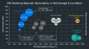
For comprehensive mechanical property tables across aerospace alloys, stainless steels, and plastics, reference our companion CNC machining materials chart.
3. Dimensional Tolerances & Geometric Repeatability
Achieving precision tolerances is where the fundamental gap between additive and subtractive manufacturing becomes most apparent on the assembly bench.
The Thermal Realities of 3D Printing
All additive processes rely on phase changes: melting and solidifying thermoplastics, photopolymerizing liquid resins via UV light, or melting metal powders with high-energy lasers.
Phase changes inevitably cause volumetric shrinkage. As extruded plastic cools from 240°C to ambient room temperature, or as molten titanium solidifies, severe thermal contraction occurs. Because thin sections cool faster than thick sections, internal thermal gradients generate residual stresses that warp, bow, and twist unsupported geometric features.
Consequently, standard industrial 3D printing tolerances are broad:
- FDM Polymers: Typical tolerance of ±0.20 mm to ±0.50 mm (±0.008 to ±0.020 in).
- SLS Nylon: Typical tolerance of ±0.15 mm to ±0.30 mm (±0.006 to ±0.012 in).
- DMLS Metal: Typical tolerance of ±0.10 mm to ±0.25 mm (±0.004 to ±0.010 in).
While these tolerances are acceptable for aesthetic enclosures or handheld form-study mockups, they fail completely when a prototype must interface with off-the-shelf mechanical hardware.
Subtractive Precision: Holding Microns
Subtractive CNC machining does not rely on thermal phase transformations. CNC mills and lathes cut room-temperature metal stock using rigid, ground carbide cutters guided by glass linear optical encoders with sub-micron positioning resolution.
Under climate-controlled workshop conditions (20°C ± 0.5°C), precision CNC machine shops routinely achieve:
- Standard Machining: ISO 2768-m (±0.10 mm / ±0.004 in).
- Precision Bores & Bearing Journals: Down to ±0.005 mm (5 μm / ±0.0002 in).
- Surface Flatness & Cylindricity: Within 0.008 mm across 150 mm spans.
For detailed ISO fit charts (H7/g6) and thermal drift mitigation techniques, consult our comprehensive guide to CNC machining tolerances.
Vivid Engineering Case Study 2: The Pressurized Pneumatic Manifold Leak
A medical robotics startup developed a compact pneumatic valve manifold operating at an internal line pressure of 1.2 MPa (174 psi). To meet an investor demonstration deadline in five days, the mechanical design lead ordered a functional prototype printed in SLS Nylon PA12.
When the 3D printed manifold was plumbed to pneumatic lines and submerged in a water inspection bath, the entire component began bubbling like an effervescent tablet.
Two critical failure modes were immediately identified:
- Inter-Particle Micro-Porosity: While the SLS nylon appeared solid to the naked eye, the microscopic spaces between sintered powder particles created a porous network of micro-capillaries that permitted compressed air to permeate directly through the manifold’s 3.0 mm walls.
- O-Ring Gland Distortion: The manifold’s face-sealing O-ring groove exhibited circularity errors of ±0.18 mm and layer stair-stepping ridges (Ra 8.5 μm). The rubber elastomeric seal could not conform to the stepped surface, resulting in blow-by leakage past the gasket.
The team engaged an AS9100/ISO-certified precision machine shop with their 3D CAD STEP file. The engineering department performed an immediate DFM review, confirmed cutter clearance, and CNC machined the manifold from a certified billet of 6061-T6 aluminum.
The part was face-milled to a flatness of 0.006 mm, the internal fluid channels were drilled and cross-ported with zero burrs, and the O-ring gland was circular-interpolated to an Ra 0.8 μm surface finish.
The CNC machined manifold was shipped via expedited air freight within 72 hours. Upon pressurized water-bath testing, it held 2.5 MPa (more than double working pressure) for 48 continuous hours with zero pressure drop.
4. Surface Roughness & Post-Processing Realities
A prototype’s surface microgeometry directly dictates its frictional performance, wear resistance, seal reliability, and visual aesthetic appeal.
The Layer Stair-Stepping Dilemma
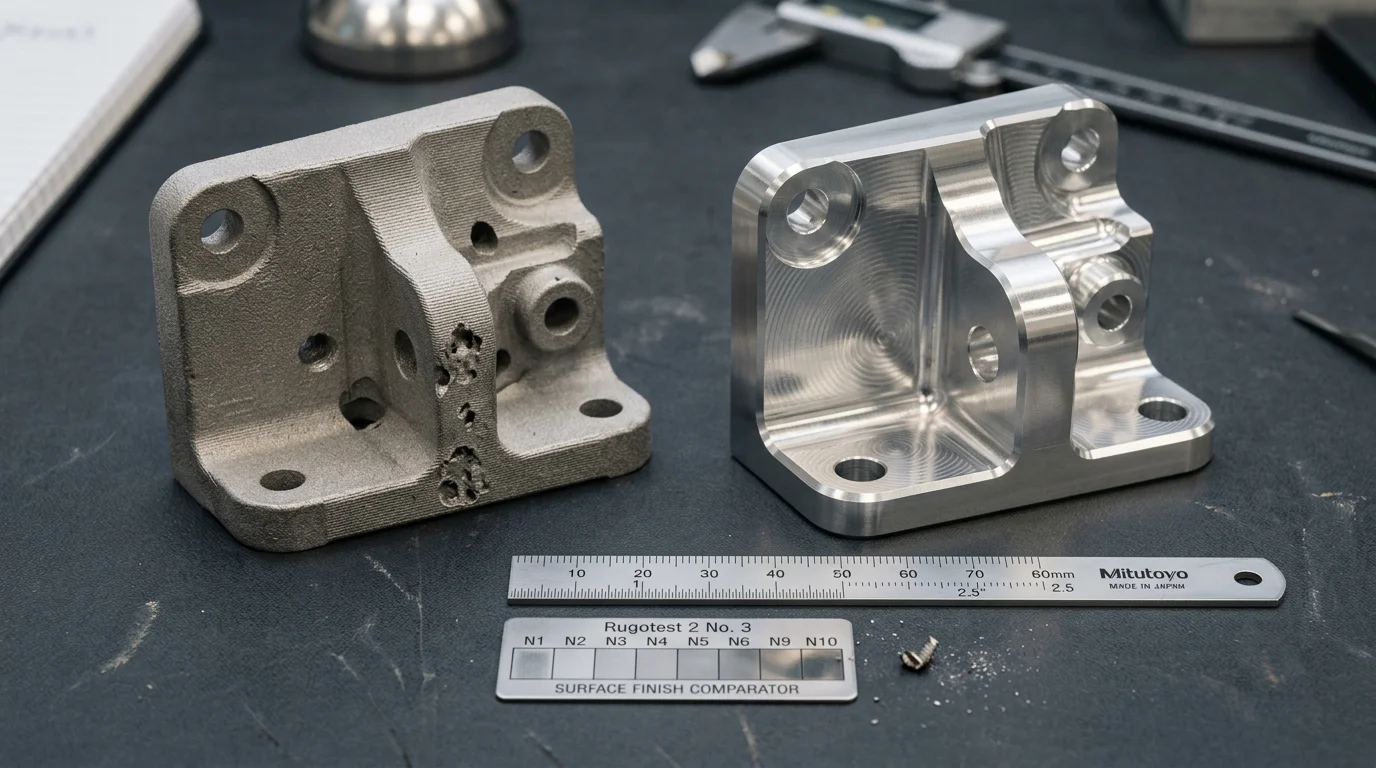
Because 3D printing constructs geometry in planar slices (typically 20 to 100 μm per layer), curved, angled, and spherical surfaces inevitably exhibit stair-stepping artifacts.
On raw metal DMLS parts, un-melted powder particles remain partially sintered to the exterior walls, producing an as-printed surface roughness of Ra 6.3 μm to Ra 12.5 μm (250 to 500 μin). On raw SLS polymer prints, surfaces resemble medium-grit sandpaper (Ra 8.0–15.0 μm).
Surfaces with this level of roughness cannot function as:
- Dynamic Shaft Seals: Micro-peaks slice rubber lip seals within minutes of rotation.
- Precision Bearing Lands: Point-contact wear rapidly induces bearing looseness.
- Cleanroom Vacuum Enclosures: Powder-trapping valleys prevent effective outgassing.
The CNC Machined Advantage
A standard CNC milling pass utilizing sharp carbide inserts delivers an as-machined surface roughness of Ra 0.8 μm to Ra 1.6 μm (32 to 63 μin) straight off the machine spindle. With high-speed single-point diamond turning or fine burnishing passes, surface roughness can be refined down to Ra 0.2 μm (8 μin) without secondary hand labor.
| Process & State | Typical Roughness (Ra) | Secondary Labor Required for Sealing |
|---|---|---|
| As-Printed FDM Polymer | 12.5 – 25.0 μm (Stair) | Extensive manual vapor smoothing/sanding |
| As-Sintered SLS Nylon PA12 | 6.3 – 12.5 μm (Gritty) | Media tumbling or chemical vapor polish |
| As-Printed DMLS Metal | 6.3 – 10.0 μm (Powder) | Support removal, wire EDM, hand polish |
| As-Machined Standard CNC Mill | 0.8 – 1.6 μm (Clean) | None (Directly seal-ready) |
| Precision CNC Turned Journal | 0.2 – 0.4 μm (Mirror) | None (Directly bearing-ready) |
Surface Finishing & Coating Compatibility
When prototypes must be anodized, electroplated, or painted to mimic end-use production parts, substrate density is paramount:
- Anodizing (Type II & Type III Hardcoat): Wrought 6061 and 7075 CNC parts anodize uniformly, creating a pristine, wear-resistant aluminum oxide ceramic layer. Conversely, DMLS AlSi10Mg contains high silicon content (approx. 10%), resulting in a patchy, dark-gray, soot-like cosmetic appearance that cannot achieve vibrant decorative colors.
- Electroplating (Nickel/Chrome/Gold): Sintered additive materials trap corrosive electroplating chemicals in their micro-porous pores. Over weeks, trapped acids leach outward, causing the plating to bubble and peel. CNC machined brass, steel, and aluminum plate cleanly with zero chemical entrapment.
To understand surface roughness metrics and coating specifications, review our complete CNC surface finish guide.
5. The Economic Break-Even Equation: Calculating Crossover Batch Volume (Ncrossover)
The commercial decision between 3D printing and CNC machining is fundamentally a battle of cost structures: Upfront Fixed Non-Recurring Engineering (NRE) vs. Per-Part Variable Run Time Cost.
The Mathematical Cost Breakdown
The unit cost of a prototype batch (N) for each process can be expressed mathematically:
For Subtractive CNC Machining:
C_CNC(N) = [ (C_CAM + C_setup) / N ] + C_cycle + C_billet
Where:
C_CAM: Upfront engineering cost to generate 3D toolpaths and verify G-code.C_setup: Machine tool setup, zero-point workholding fixturing, and tool touch-offs.C_cycle: Spindle run-time cost per part (cutting time multiplied by machine hourly rate).C_billet: Raw material stock block cost minus swarf recycling credit.
For Additive 3D Printing:
C_3DP(N) = [ C_prep / N ] + (t_build × R_printer) + (m_part × P_material) + C_post
Where:
C_prep: Slicing software preparation and build-tray layout (virtually negligible).t_build: Total laser scanning or extrusion hours required to build the part’s volume.R_printer: Industrial additive machine hourly amortization rate.m_part × P_material: Specialized photopolymer resin, nylon powder, or metal powder cost.C_post: Labor cost for support structure removal, wire EDM cutoff, and bead blasting.
The Crossover Curve Dynamics
Because 3D printing requires almost zero setup time or specialized fixturing, its cost curve starts low for a single unit (N=1). However, the variable cost per part remains nearly flat as volume increases; printing the 20th part takes exactly as long and consumes just as much expensive specialized powder as printing the 1st part.
Conversely, CNC machining carries an upfront setup hump (Csetup) to program toolpaths, set work offsets, and clamp raw billets. However, once the machine is dialed in, the spindle cuts at blistering speeds—often completing a part in minutes rather than hours. Raw billet aluminum costs just 4 to 6 per kilogram, compared to 90 to 180 per kilogram for spherical DMLS aluminum powder.
As a result, as batch volume (N) increases, the CNC fixed setup cost amortizes rapidly across the batch:
Batch Crossover Point (N_crossover):
When C_CNC(N) ≤ C_3DP(N)
For Metal Components: N_crossover ≈ 3 to 15 pieces
For Polymer Components: N_crossover ≈ 10 to 30 pieces
Vivid Engineering Case Study 3: The 20-Piece IP67 Sensor Housing Real-World Bill
An industrial IoT hardware manufacturer designed an outdoor IP67 environmental sensor housing measuring 120 × 80 × 40 mm with internal electronics mounting bosses and a perimeter gasket tongue. The company needed 20 prototype units for field testing across agricultural customer sites.
The hardware lead evaluated two manufacturing quotations:
| Cost Factor | DMLS Metal 3D Printing (AlSi10Mg) | CNC Machining (6061-T6 Aluminum) |
|---|---|---|
| Upfront CAM & Fixture Setup | 45 (Digital slicing prep) | 280 (CAM toolpathing & soft jaws) |
| Machine Run Time per Unit | 9.5 hours build time per part | 14 minutes spindle cutting time |
| Machine Hourly Billing Rate | 32 / hour | 65 / hour |
| Machine Run Cost per Unit | 304.00 | 15.17 |
| Raw Material Stock per Unit | 65.00 (Gas-atomized metal powder) | 12.50 (Wrought 6061 extrusion) |
| Secondary Post-Processing | 35.00 (Support removal & blast) | 4.50 (Vibratory de-burring) |
| Total Cost per Part (N = 20) | 406.25 / unit | 46.17 / unit |
| TOTAL BATCH INVOICE (20 pcs) | 8,125.00 | 923.40 |
| Lead Time to Delivery | 9 Business Days (Queue bottleneck) | 4 Business Days (Rapid air ship) |
The Financial Result: CNC machining saved the customer 7,201.60—an 88.6% cost reduction—while delivering superior structural strength, watertight gasket sealing, and an aerospace-grade Type II clear anodized finish in half the calendar lead time.
For an economic breakdown of machine hourly rates and batch amortization equations, consult our detailed analysis on CNC machining cost.
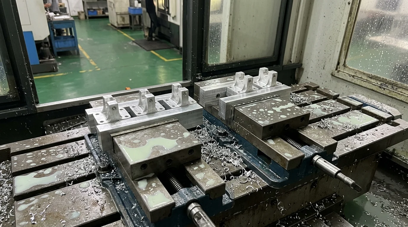
6. Hybrid Manufacturing: Combining 3D Printing and CNC Machining
In modern aerospace, automotive, and high-performance hardware, the most sophisticated manufacturing teams do not view 3D printing and CNC machining as mutually exclusive rivals. Instead, they leverage Hybrid Additive-Subtractive Workflows.
The Hybrid Concept
Hybrid manufacturing combines the geometric freedom of additive manufacturing with the micron-level precision and surface quality of subtractive CNC:
- Additive Near-Net Pre-Form: A laser powder bed fusion (DMLS) or wire-arc additive manufacturing (WAAM) cell builds a near-net shape blank featuring complex internal cavities, lightweight bionic lattices, or conformal cooling channels that would be impossible to drill with rotary cutters.
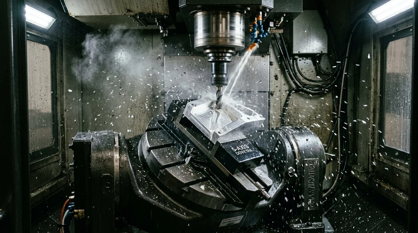
- Subtractive CNC Finish Machining: The printed blank is transferred to a 5-axis CNC machining center. The mill machines critical bearing bores, O-ring seal lands, precision datums, and tapped bolt circles to sub-micron accuracy.
Vivid Engineering Case Study 4: The Electric Racecar Inverter Cold Plate
A Formula Student electric racing team designed an ultra-compact liquid cooling cold plate for a 150 kW silicon-carbide inverter module. The interior of the cold plate featured an intricate network of three-dimensional, curved, helical micro-channels designed to maximize liquid coolant turbulence and heat transfer surface area.
No standard gun drill or 5-axis ball end mill could access these curved interior channels. However, the outer face of the cold plate required extreme flatness (±0.005 mm) to ensure intimate thermal contact with the flat ceramic inverter power modules, along with M4 tapped blind holes that could withstand 2.5 N·m assembly torque.
The team deployed a hybrid protocol:
- Step 1 (DMLS Additive): The cold plate was 3D printed in AlSi10Mg aluminum with the internal conformal fluid channels fully enclosed. The exterior CAD model was programmed with +2.5 mm of extra “green stock” on all exterior mating flanges.
- Step 2 (CNC 5-Axis Finishing): The additive blank was mounted in a precision hydraulic vise on a 5-axis 5-axis CNC machining center. An automated Renishaw touch probe scanned the exterior printed datums to establish the coordinate workpiece zero.
- The mill skimmed the top face to an Ra 0.4 μm mirror finish, interpolated the coolant port O-ring glands, and rigid-tapped the blind bolt patterns to exact thread depths.
The finished hybrid cold plate delivered superior thermal dissipation while sealing against 0.6 MPa fluid pressure with zero leaks.
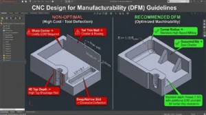
To optimize 3D CAD models for rotary cutter accessibility and avoid unnecessary manufacturing operations, consult our CNC machining design guide.
7. Rapid Engineering Decision Matrix & Procurement Checklist
To help your engineering team quickly select the optimal prototyping process for your next hardware sprint, use this structured decision framework:
| Engineering Requirement | Recommended Process | Critical Decision Driver |
|---|---|---|
| Dynamic cyclical fatigue / vibration | CNC Machining (Wrought) | Isotropic grain structure |
| Airtight pneumatic / hydraulic body | CNC Machining (Zero Pores) | Sintered 3D prints leak |
| Production alloy required (6061/7075) | CNC Machining (Mill Certs) | Certified wrought traceability |
| Batch quantity N >= 5 pieces (Metal) | CNC Machining | CNC setup cost amortizes fast |
| Standard internal threads (M2 to M12) | CNC Machining (Rigid Tap) | 3DP threads strip easily |
The 5-Minute Prototyping Decision Flowchart
- Does the component require internal hollow channels, bionic organic voids, or enclosed fluid passageways that a rotary tool cannot touch via line of sight?
- YES → Choose 3D Printing (or Hybrid DMLS + CNC finishing).
- NO → Proceed to Question 2.
- Does the design feature precision mechanical interfaces (bearing journals with ±0.010 mm tolerances, press-fit dowel pins, or dynamic seal lands)?
- YES → Choose CNC Machining. Additive thermal shrinkage will yield loose fits or require manual hand-reaming.
- NO → Proceed to Question 3.
- Will the prototype endure high dynamic tensile loads, shock impacts, or cyclical vibration during functional bench testing?
- YES → Choose CNC Machining. Avoid catastrophic Z-axis interlaminar delamination.
- NO → Proceed to Question 4.
- Is the required prototype quantity 5 pieces or greater?
- YES → Choose CNC Machining. Rapid spindle cutting speeds and low raw stock costs make CNC substantially more economical than 3D printing.
- NO → Proceed to Question 5.
- Does the part need functional surface treatments (Type III Hardcoat Anodizing, Passivation, or Mirror Chrome Plating)?
- YES → Choose CNC Machining. Wrought metal billets finish flawlessly without outgassing or chemical bleed-out.
- NO → Choose 3D Printing for rapid, low-cost form evaluation.
8. Fast-Track Your Functional Prototypes with Precision CNC
Whether you need a single precision-machined aluminum prototype to validate a critical bearing press-fit, or a bridge batch of 50 units for rigorous pilot customer field trials, CNMP provides the engineering expertise, equipment, and certified quality management systems required to de-risk your development pipeline.
Why Engineering Teams Choose Certified Prototyping Specialists:
- 1-Piece Rapid Prototyping (MOQ = 1): We embrace single-piece validation runs with rapid 3 to 5 business day delivery, eliminating prohibitive minimum order quantities.
- Certified Precision Tolerances: High-precision 3-axis, 4-axis, and simultaneous 5-axis machining centers delivering tolerances down to ±0.005 mm (5 μm).
- Automotive OEM Credentials: Tier manufacturing supplier experience producing high-reliability air suspension valve blocks for Arnott and leak-free fluid fittings for Dytech.
- Comprehensive In-House Metrology: Every prototype is verified with Mitutoyo digital micrometers, optical surface profilometers, and Zeiss Coordinate Measuring Machines (CMM), complete with Full Inspection Reports (FAI).
- Full Spectrum Materials & Finishing: Complete stock of certified 6061/7075 aluminum, 304/316/17-4PH stainless steel, titanium, brass, Delrin POM, and PEEK, backed by in-house anodizing, bead blasting, passivation, and plating.
Ready to Validate Your Hardware Design?
Upload your 3D CAD files (STEP, IGES, or Parasolid) and 2D engineering drawings (PDF with critical tolerances and thread callouts) to receive an interactive, physics-grounded DFM evaluation and an itemized manufacturing quote within 24 hours.