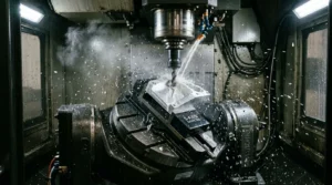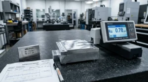
In mechanical engineering and precision manufacturing, defining the correct CNC machining tolerance represents the critical boundary between kinematic assembly function and catastrophic field failure. Every subtractive manufacturing operation encounters physical variances resulting from cutting tool deflection, thermal expansion, spindle runout, material elasticity, and machine axis backlash. Understanding the practical capabilities of multi-axis machining centers and international tolerance standards allows design engineers and procurement teams to achieve micron-level precision without imposing exponential manufacturing cost penalties.
Specifying tolerances requires balancing geometric necessity against production physics. Sourcing custom CNC machining services with overly tight blanket callouts inflates machining cycle times, mandates secondary finishing passes, spikes scrap rates, and forces expensive coordinate metrology. Conversely, ambiguous or loose tolerances risk loose fits, fluid leaks in pressurized manifolds, and kinematic binding in rotating assemblies.
At-a-Glance: CNC Machining Tolerance Benchmarks & Capability Matrix
| Tolerance Classification | Linear Dimension Band (Typical) | Typical Manufacturing Processes | Secondary Operations & Metrology Required | Cost Multiplier (vs. Baseline) |
|---|---|---|---|---|
| Standard Commercial (ISO 2768-m) | ±0.100 mm to ±0.200 mm (±0.004 in to ±0.008 in) | Standard 3-axis VMC milling, rough turning, drilling | Standard high-speed roughing; manual vernier calipers and digital height gauges | 1.0x (Baseline) |
| Precision CNC Tier | ±0.025 mm to ±0.050 mm (±0.001 in to ±0.002 in) | 3-axis / 4-axis CNC milling, precision CNC lathe turning | Dedicated semi-finishing and finishing toolpaths; micrometers and bore gauges | 1.3x – 1.5x |
| High-Precision Tier | ±0.010 mm to ±0.015 mm (±0.0004 in to ±0.0006 in) | High-end 5-axis milling, Swiss screw machining, live-tool turning | Micro-grain carbide tooling, spindle warm-up stabilization; optical comparators | 1.8x – 2.2x |
| Micro-Precision / Premium Zone | ±0.005 mm (±0.0002 in / 5 µm) | Precision cylindrical grinding, jig boring, Wire EDM, temperature-controlled 5-axis | 20°C thermal soaking, diamond (PCD) tooling, 100% Zeiss CMM probing | 3.0x – 4.5x |
| Sub-Micron Ultra-Precision | ±0.001 mm to ±0.002 mm (1–2 µm) | Ultra-precision lapping, diamond turning, honing | Specialized optical cleanroom, laser interferometry, multi-hour thermal soak | 6.0x – 10.0x+ |

What Are CNC Machining Tolerances? Dimensional vs. Geometric (GD&T)
A tolerance defines the total permissible variation of a physical dimension from its nominal design value. In mechanical engineering drawings, tolerances are broadly divided into two distinct domains: traditional dimensional tolerances and geometric dimensioning and tolerancing (GD&T).
Dimensional Tolerances: Linear, Angular, and Diametral
Dimensional tolerances dictate the allowable size variation of a specific physical feature—such as the length of a prismatic block, the diameter of a turned shaft, or the depth of a milled pocket. These callouts are expressed through three standard formats:
- Bilateral Tolerances: The allowable variance is distributed either symmetrically or asymmetrically across both sides of the nominal dimension. For example, a nominal shaft dimension of 25.00 mm ± 0.05 mm defines an acceptable upper specification limit (USL) of 25.05 mm and a lower specification limit (LSL) of 24.95 mm, yielding a total tolerance zone of 0.10 mm.
- Unilateral Tolerances: Variance is permitted in only one direction relative to the nominal dimension, while the opposing direction carries zero variance. For example, an internal bore specified as Ø30.00 mm +0.03/-0.00 mm ensures that the mating shaft can never experience interference caused by undersized machining.
- Limit Dimensions: The upper and lower allowable limits are explicitly stated in place of a nominal value (e.g., 49.95 / 49.90 mm). This format eliminates mathematical interpretation on the machine shop floor.
Geometric Dimensioning and Tolerancing (GD&T per ASME Y14.5 / ISO 1101)
While dimensional tolerances control feature size, they fail to control three-dimensional geometry, orientation, and relationship between features. A cylindrical pin can measure within nominal dimensional limits at every discrete cross-section yet remain bowed, oval, or tapered.
GD&T establishes a mathematical language that controls form, orientation, location, and runout relative to established physical datums:
- Form Controls: Flatness, straightness, circularity, and cylindricity operate independently without requiring a datum reference.
- Orientation Controls: Perpendicularity, parallelism, and angularity govern feature alignment relative to designated primary and secondary datum planes.
- Location Controls: True Position defines a cylindrical or planar tolerance zone within which the center axis or center plane of a feature must lie relative to a Datum Reference Frame (DRF: Primary A, Secondary B, Tertiary C). True position eliminates square tolerance zone corners, unlocking up to 57% additional usable manufacturing tolerance when Maximum Material Condition (MMC) is specified.
- Runout Controls: Circular runout and total runout evaluate rotational coaxiality and surface wobble on turned shafts and rotating spindles.
Standard CNC Machining Tolerance Charts: ISO 2768 & DIN Standards
When an engineering drawing does not explicitly specify a numerical tolerance for a specific feature, manufacturing facilities default to international general tolerance standards. The globally recognized benchmark for subtractive machining is ISO 2768, split into two parts: ISO 2768-1 (linear and angular dimensions) and ISO 2768-2 (geometrical tolerances).
Engineering drawings typically declare this baseline in the title block using the standard annotation: "General tolerances per ISO 2768-mK" (where m denotes medium linear tolerance and K denotes medium geometrical tolerance).
ISO 2768-1: Linear Dimensions Tolerance Chart
ISO 2768-1 defines four tolerance classes:
- Class f (Fine): Precision mechanical engineering, laboratory instruments, and tight aerospace assemblies.
- Class m (Medium): The global default standard for general precision CNC milling and turning.
- Class c (Coarse): Non-critical industrial weldments, rough forgings, and structural fabrications.
- Class v (Very Coarse): Open cast components with wide dimensional bands.
| Nominal Dimension Band (mm) | Class f (Fine) Permissible Deviation | Class m (Medium) Permissible Deviation | Class c (Coarse) Permissible Deviation | Class v (Very Coarse) Permissible Deviation |
|---|---|---|---|---|
| 0.5 to 3 | ±0.05 mm | ±0.10 mm | ±0.20 mm | — |
| Over 3 to 6 | ±0.05 mm | ±0.10 mm | ±0.30 mm | ±0.50 mm |
| Over 6 to 30 | ±0.10 mm | ±0.20 mm | ±0.50 mm | ±1.00 mm |
| Over 30 to 120 | ±0.15 mm | ±0.30 mm | ±0.80 mm | ±1.50 mm |
| Over 120 to 400 | ±0.20 mm | ±0.50 mm | ±1.20 mm | ±2.50 mm |
| Over 400 to 1,000 | ±0.30 mm | ±0.80 mm | ±2.00 mm | ±4.00 mm |
| Over 1,000 to 2,000 | ±0.50 mm | ±1.20 mm | ±3.00 mm | ±6.00 mm |
ISO 2768-2: Geometrical Tolerances Chart
ISO 2768-2 establishes default geometrical tolerances across three classes: H (tightest), K (medium), and L (coarse). These control features without individual GD&T feature control frames.
| Geometrical Characteristic | Nominal Dimension Band (mm) | Class H Permissible Deviation | Class K Permissible Deviation | Class L Permissible Deviation |
|---|---|---|---|---|
| General Flatness & Straightness | Up to 10 | 0.02 mm | 0.05 mm | 0.10 mm |
| Over 10 to 30 | 0.05 mm | 0.10 mm | 0.20 mm | |
| Over 30 to 100 | 0.10 mm | 0.20 mm | 0.40 mm | |
| Over 100 to 300 | 0.20 mm | 0.40 mm | 0.80 mm | |
| Perpendicularity | Up to 100 | 0.20 mm | 0.40 mm | 0.60 mm |
| Over 100 to 300 | 0.30 mm | 0.60 mm | 1.00 mm | |
| Circular Runout | All nominal sizes | 0.10 mm | 0.20 mm | 0.50 mm |
CNC Machining Tolerance Capabilities by Process
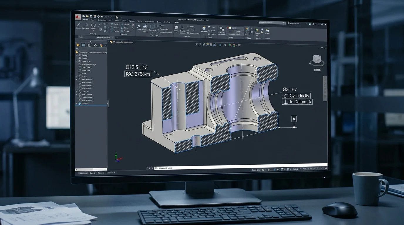
Achievable tolerances are governed by the mechanical kinematics, tool stiffness, and dynamic rigidity of the specific machine tool. A 5-axis machining center, a Swiss screw lathe, and an electrical discharge machine exhibit fundamentally divergent physical error profiles.
Process Capability Comparison
| Machining Process | Standard Commercial Tolerance | Tightest Practical Tolerance | Typical Features Produced | Primary Kinematic Limiter |
|---|---|---|---|---|
| 3-Axis & 4-Axis CNC Milling | ±0.050 mm (±0.002 in) | ±0.010 mm (±0.0004 in) | Prismatic enclosures, bracket faces, stepped pockets | Tool overhang deflection, multi-setup repositioning errors |
| 5-Axis Simultaneous Milling | ±0.025 mm (±0.001 in) | ±0.005 mm (±0.0002 in) | Impellers, turbine blades, complex compound angled bores | Trunnion/rotary table kinematic calibration, thermal drift |
| CNC Lathe & Mill-Turn Centers | ±0.025 mm (±0.001 in) | ±0.005 mm (±0.0002 in) | Precision stepped shafts, bushings, threaded hydraulic fittings | Chucking pressure distortion, radial tool wear |
| Swiss Screw Machining | ±0.010 mm (±0.0004 in) | ±0.003 mm (±0.00012 in) | Miniature pins, medical implants, slender shafts (L/D > 10) | Guide bushing clearance, bar stock roundness variation |
| Precision Cylindrical & Surface Grinding | ±0.003 mm (±0.00012 in) | ±0.001 mm (±0.00004 in) | Hardened bearing journals, gage blocks, ultra-flat seal faces | Abrasive wheel dressing accuracy, spark-out dwell time |
| Wire EDM (Electrical Discharge) | ±0.005 mm (±0.0002 in) | ±0.002 mm (±0.00008 in) | Internal keyways, extrusion dies, thin-walled precision slots | Wire lag during direction changes, dielectric fluid flushing |
3-Axis vs. 5-Axis Milling: Eliminating Datum Stack-Up
In traditional 3-axis precision CNC milling services, complex parts requiring machining on multiple faces necessitate multiple fixture clampings. Every time a part is flipped and re-clamped in soft jaws, human operator variance and microscopic chip contamination introduce datum transfer errors of 0.015 mm to 0.040 mm.
Advanced 5-axis CNC machining overcomes this limitation through “Done-in-One” single-setup processing. Because the cutting tool accesses 5 sides of the workpiece in a continuous kinematic coordinate system, true position tolerances between intersecting bores and compound angled faces can be maintained down to ±0.005 mm.
CNC Turning & Swiss Machining Dynamics
For cylindrical geometries, precision CNC turning provides higher concentricity than milling because the workpiece rotates symmetrically about a rigid spindle centerline. However, long slender parts suffer from radial deflection under tool cutting forces:
y = (F × L3) / (3 × E × I) ∝ L3 / d4
Where deflection (y) increases with the cube of length (L) and decreases with the fourth power of diameter (d). When the length-to-diameter ratio (L/D) exceeds 4:1, standard lathes experience chatter and taper. In contrast, Swiss screw machines feed the workpiece through a carbide guide bushing directly adjacent to the cutting insert, eliminating overhang and enabling ±0.003 mm diameter consistency across long, thin components.
Material Stability, Thermal Expansion & Machinability Impact on Tolerances
Machine tool accuracy represents only half the precision equation. Workpiece material physics—specifically the Coefficient of Thermal Expansion (CTE), residual internal stresses, modulus of elasticity, and thermal conductivity—frequently dictates whether a tight tolerance can physically survive manufacturing and inspection.
The Physics of Thermal Drift
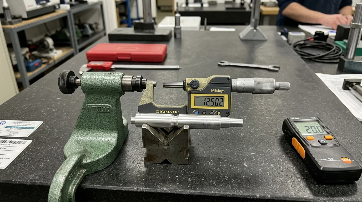
Machining generates friction and shear heat. When parts are inspected or operated at temperatures differing from the universal international measurement standard of 20.0°C (68.0°F), dimensions expand or contract according to:
Δ L = α × L_0 × Δ T
Where α is the material linear CTE, L_0 is the nominal length, and Δ T is the temperature differential from 20.0°C.
For aerospace-grade 6061-T6 aluminum (α ≈ 23.1 × 10^{-6}/K), an ambient shop floor temperature rise of just 5.0°C (9.0°F) causes a 100.0 mm dimension to expand by:
ΔL = (23.1 × 10⁻⁶ / K) × 100.0 mm × 5.0 K = 0.0115 mm (11.5 μm)
An expansion of 11.5 µm completely consumes and exceeds a ±0.005 mm (10 µm total) tolerance envelope before taking into account cutting tool wear or machine backlash. Holding micro-precision requires temperature-controlled machining enclosures and dedicated 4-hour thermal soaking on granite surface plates prior to quality sign-off.
Comprehensive Material Thermal & Tolerance Capability Matrix
| Material Category & Grade | Coefficient of Thermal Expansion (α at 20°C) | Dimensional Shift per 100 mm at ΔT = 5°C | Standard Machining Tolerance | Tightest Practical Tolerance | Key Physical Machining Challenge |
|---|---|---|---|---|---|
| Aluminum 6061-T6 / 7075-T6 | 23.1 × 10⁻⁶/K | +11.5 µm (+0.0115 mm) | ±0.050 mm | ±0.005 mm | High thermal expansion; requires stress-relieved stock (T651) to prevent warping upon pocket roughing |
| Carbon Steel 1045 / Alloy 4140 | 11.5–12.2 × 10⁻⁶/K | +5.8 µm (+0.0058 mm) | ±0.025 mm | ±0.005 mm | High elastic modulus; highly predictable thermal stability; excellent for press-fit bearing bores |
| Stainless Steel 304 / 316L | 16.0–17.0 × 10⁻⁶/K | +8.2 µm (+0.0082 mm) | ±0.050 mm | ±0.010 mm | Severe work hardening and low thermal conductivity; localized heat buildup induces thermal taper |
| Free-Cutting Brass C360 | 20.5 × 10⁻⁶/K | +10.2 µm (+0.0102 mm) | ±0.025 mm | ±0.005 mm | Exceptional machinability and zero internal stress; short brittle chips maintain dimensional stability |
| Titanium Ti-6Al-4V (Grade 5) | 8.6 × 10⁻⁶/K | +4.3 µm (+0.0043 mm) | ±0.050 mm | ±0.015 mm | Low elastic modulus (110 GPa) causes high workpiece springback; extreme heat concentrates at tool tip |
| Acetal / Delrin (POM-C) | 110.0 × 10⁻⁶/K | +55.0 µm (+0.0550 mm) | ±0.100 mm | ±0.025 mm | High thermal expansion; vise clamping easily crushes thin walls; internal stress requires pre-annealing |
| PEEK (Polyetheretherketone) | 47.0 × 10⁻⁶/K | +23.5 µm (+0.0235 mm) | ±0.050 mm | ±0.015 mm | Rigid semi-crystalline engineering thermoplastic; holds tighter tolerances than POM but requires sharp carbide |
| Nylon 6 / PA66 | 90.0 × 10⁻⁶/K | +45.0 µm (+0.0450 mm) | ±0.150 mm | ±0.050 mm | High hygroscopic water absorption causes swelling up to 2%–3% by volume; unsuited for tight fits |
For detailed guidance on alloy machinability ratings and temper designations, consult the comprehensive CNC machining materials engineering reference.
Surface Roughness (Ra) and Its Mechanical Interlock with Tolerances
A fundamental rule of metrology states: dimensional tolerance cannot be held or measured to a resolution finer than the surface texture upon which it resides. Surface finish (roughness) and dimensional tolerance are mechanically and mathematically interlocked.
The Peak-to-Valley (Rz) Reality
Surface roughness is conventionally specified in Roughness Average (Ra), representing the arithmetical mean deviation of the surface profile. However, cutting tool passes create microscopic peaks and valleys. The average maximum peak-to-valley height (R_z) on a machined surface typically measures 4 to 6 times greater than the Ra value:
Rz ≈ 4 to 6 × Ra
If an engineering drawing specifies a tight linear tolerance of ±0.005 mm (a total tolerance zone of 0.010 mm = 10 µm) on a milled face with a commercial finish of Ra 3.2 μm, the peak-to-valley roughness (R_z) spans:
Rz ≈ 5 × 3.2 μm = 16.0 μm
The microscopic surface irregularities (16.0 µm) exceed the entire allowable dimensional boundary (10.0 µm). Depending on whether a metrology probe lands on a peak or in a valley, the measurement fluctuates wildly, making statistical process verification impossible.
The Golden Rule of Tolerance and Roughness Compatibility
As an engineering best practice, the surface roughness (Ra) should not exceed 10% to 20% of the total dimensional tolerance zone (T):
Ra ≤ 0.10 × T (Ideal) | Ra ≤ 0.20 × T (Maximum Allowable)
| Machining Operation | Practical Surface Roughness (Ra) | Resulting Peak-to-Valley (Rz) | Minimum Compatible Tolerance Zone (T) | Suitable Application Callout |
|---|---|---|---|---|
| Rough Milling / Turning | Ra 3.2 to 6.3 µm (125–250 µin) | 16 to 35 µm | ≥ ±0.100 mm (≥ 200 µm zone) | Non-mating clearance faces, structural brackets |
| Standard Finish Milling | Ra 1.6 to 3.2 µm (63–125 µin) | 8 to 16 µm | ±0.050 mm (100 µm zone) | Bolted flange joints, general locating surfaces |
| Fine Finish Milling / Turning | Ra 0.8 to 1.6 µm (32–63 µin) | 4 to 8 µm | ±0.025 mm (50 µm zone) | Static dynamic O-ring sealing grooves, alignment registers |
| Precision Turning / Burnishing | Ra 0.4 to 0.8 µm (16–32 µin) | 2 to 4 µm | ±0.010 mm (20 µm zone) | Precision sliding fits (g6/h6), valve spools |
| Cylindrical / Surface Grinding | Ra 0.1 to 0.4 µm (4–16 µin) | 0.5 to 2 µm | ±0.003 to ±0.005 mm (6–10 µm zone) | High-speed ball bearing seats, hydraulic piston seals |
| Lapping & Diamond Honing | Ra 0.025 to 0.1 µm (1–4 µin) | 0.1 to 0.5 µm | ±0.001 mm (2 µm zone) | Optical mirrors, fuel injector sealing needles |
Surface Coating Pre-Compensation
Dimensional callouts must account for post-machining surface treatments. Anodizing and electroplating deposit measurable material layers that directly alter final dimensions:
- Type II Sulfuric Anodizing (MIL-A-8625): Typically adds 5 to 10 µm (0.005–0.010 mm) coating thickness per surface, resulting in a diametral growth of 10 to 20 µm on external pins and a corresponding shrinkage on internal bores.
- Type III Hardcoat Anodizing: Generates 25 to 50 µm (0.025–0.050 mm) layer thickness. Crucially, Hardcoat penetrates approximately 50% into the substrate metal and grows 50% outward from the original surface. A 50 µm hardcoat layer causes an external diameter to swell by 50 µm and an internal bore to shrink by 50 µm.
- Passivation & Chemical Film (Chromate / Alodine): Negligible dimensional impact (< 1 µm), safely applied after machining without pre-compensation.
Machining drawings must explicitly specify whether tolerance limits apply before coating or after coating. For detailed treatment specifications, refer to our CNC surface finish guide.
Tolerance Economics: The Exponential Cost Curve of the ±0.005mm Premium Zone
In precision manufacturing, machining cost does not scale linearly with tolerance tightness; it increases exponentially. Understanding the CNC machining cost curve prevents engineering teams from unnecessarily inflating part budgets.
Why the ±0.005mm Zone Costs 3x to 4x More
When an engineer tightens a tolerance from standard commercial (±0.10 mm) to precision (±0.025 mm), the machinist reduces feed rates and programs a semi-finishing pass. However, crossing the threshold into the ±0.005 mm (5 µm / ±0.0002 in) premium zone triggers fundamental shifts in shop floor execution:
- Cycle Time Expansion: Roughing and finishing cannot occur in rapid succession. The part must undergo rough machining, rest to relieve localized heat and clamping stress, and then undergo delicate micro-finishing passes with brand-new solid carbide or polycrystalline diamond (PCD) tooling.
- Machine Kinematics & Linear Scales: Standard machining centers with optical rotary encoders cannot reliably compensate for thermal ballscrew growth. Machining ±0.005 mm requires high-end machines equipped with pressurized optical glass scales (0.1 µm feedback) and direct-drive chilled spindles.
- Scrap Rate Exposure: Under standard tolerances, process capability indices (C_p and C_{pk}) readily exceed 1.67. In a 10 µm total tolerance window, a 2 µm tool wear variance or a minor chip trapped in a vise jaw produces an immediate out-of-spec scrap part.
- Metrology & Inspection Bottlenecks: Calipers and standard micrometers are physically incapable of verifying 5 µm limits. Every finished batch must undergo a mandatory 4-hour thermal soak on a Grade 00 granite surface plate before automated inspection on a Zeiss or Mitutoyo Coordinate Measuring Machine (CMM).
Real-World Cost Case Study: Hydraulic Valve Spool Housing
Consider an illustrative engineering example of a precision 100 mm × 80 mm × 40 mm 6061-T6 aluminum hydraulic valve body with four mounting holes and a central spool bore:
- Scenario A (Commercial ISO 2768-m throughout, bore ±0.05 mm): Machined on a standard 3-axis VMC in 2 setups. Cycle time: 14 minutes. Inspection: 2 minutes with manual bore gauge. Unit Price (100 pcs): $22.50.
- Scenario B (Selective CTQ: ISO 2768-m body, central spool bore ±0.005 mm): Machined on a 5-axis center; roughing followed by fine boring head; CMM FAI report on bore roundness and cylindricity. Unit Price (100 pcs): $34.80 (+54% increase).
- Scenario C (Over-Toleranced Blanket: ±0.005 mm applied to all external faces and holes): Requires multi-pass face milling, temperature soak, continuous tool offsets, 100% full-profile CMM scanning. Unit Price (100 pcs): $89.00 (+295% increase).
Applying tight tolerances selectively to functional features preserves assembly performance while saving nearly $55 per part compared to blanket over-tolerancing.
How to Specify Tolerances on Technical Drawings: 6 DFM Rules
Clear, standardized engineering drawings eliminate ambiguity between design intent and machine shop execution. Adhering to these six DFM rules ensures manufacturing feasibility and competitive quoting.
Rule 1: Declare a Standard General Tolerance in the Title Block
Never leave non-critical dimensions floating without an overarching tolerance standard. Specify a standard ISO 2768 or ASME callout in the drawing title block: "UNLESS OTHERWISE SPECIFIED, TOLERANCES ACCORDING TO ISO 2768-mK." This immediately establishes acceptable deviations for 90% of part features—such as external chamfers, clearance bolt holes, and overall stock dimensions—saving drafting time and manufacturing expense.
Rule 2: Balloon Critical-to-Quality (CTQ) Dimensions
Isolate the specific functional features that affect product operation: bearing press-fits, seal gland widths, dowel pin locating holes, and hydraulic spool interfaces. Flag these dimensions with formal inspection balloons (e.g., CTQ-01, CTQ-02) and provide explicit numerical bilateral or unilateral limits. Quality assurance teams use these balloon callouts to structure the First Article Inspection (FAI) report.
Rule 3: Construct Functional Datum Reference Frames (DRF)
Avoid creating floating GD&T feature control frames without datums. Structure your Datum Reference Frame to mirror the actual physical assembly hierarchy:
- Datum A (Primary): The primary flat mating face (constraining 3 degrees of freedom: 1 translation, 2 rotations).
- Datum B (Secondary): The primary locating bore or central axis (constraining 2 translation degrees of freedom).
- Datum C (Tertiary): An alignment slot or clocking pin hole (constraining the final rotational degree of freedom).
Rule 4: Adopt ISO 286 / ANSI B4.1 Standardized Fits
Rather than specifying arbitrary decimal numbers for shafts and holes, utilize standardized fit classifications:
- Clearance Fits (e.g., H7/g6 or H8/f7): Guarantees running or sliding clearance for rotating shafts and guide pins.
- Transition Fits (e.g., H7/k6 or H7/m6): Provides accurate location with light press or hand mallet assembly without play.
- Interference / Press Fits (e.g., H7/p6 or H7/s6): Rigid permanent assembly for bushing sleeves and bearing outer rings without keyways.
Machine shops possess calibrated plug gauges, reamers, and boring heads tailored specifically to ISO fit standards, reducing custom tooling expenses.
Rule 5: Eliminate Chained Dimensioning (Prevent Stack-Up)
Never dimension a sequence of features point-to-point in a continuous chain. In chain dimensioning, the tolerance of each individual feature accumulates across the component:
T_{total} = \sum_{i=1}^{n} T_i
A chain of five features toleranced at ±0.10 mm yields an overall positional uncertainty of ±0.50 mm at the final feature. Instead, employ baseline dimensioning or coordinate dimensioning referenced directly from Datum A and Datum B.
Rule 6: Explicitly Annotate Coating Application State
Always state whether dimensional and geometric limits apply before or after surface treatment: "ALL DIMENSIONS AND TOLERANCES APPLY AFTER FINAL TYPE III HARDCOAT ANODIZING AND PASSIVATION." If a precision bore must remain bare aluminum or steel to hold an exact tolerance, explicitly note: "MASK BORE Ø20.000 +0.010/-0.000 PRIOR TO ANODIZING."
Quality Verification & Metrology: Proving Microns on the Shop Floor
A tolerance is only as reliable as the metrology equipment employed to inspect it. In a certified manufacturing environment, metrology tools are selected according to the Gage Maker’s Rule (10:1 Rule): the measuring instrument must possess an accuracy and resolution ten times finer than the total tolerance zone being inspected.
Metrology Instrument Selection by Tolerance Tier
| Metrology Equipment | Measurement Resolution | Calibration Uncertainty | Minimum Inspectable Tolerance Band | Best Used For |
|---|---|---|---|---|
| Vernier / Digital Caliper | 0.01 mm (0.0005 in) | ±0.020 mm | ±0.100 mm (0.20 mm zone) | Quick check of overall stock lengths, web thicknesses, non-critical hole depths |
| Digital Outside Micrometer | 0.001 mm (0.00005 in) | ±0.002 mm | ±0.010 mm (0.02 mm zone) | Precision turned shaft diameters, thickness of ground plates |
| Three-Point Internal Bore Micrometer | 0.001 mm (0.00005 in) | ±0.003 mm | ±0.015 mm (0.03 mm zone) | Internal diameters, reamed bushing bores |
| Granite Plate & Digital Height Gauge | 0.001 mm (0.00005 in) | ±0.003 mm | ±0.015 mm (0.03 mm zone) | Step heights, slot depths, flatness baseline checks relative to Datum A |
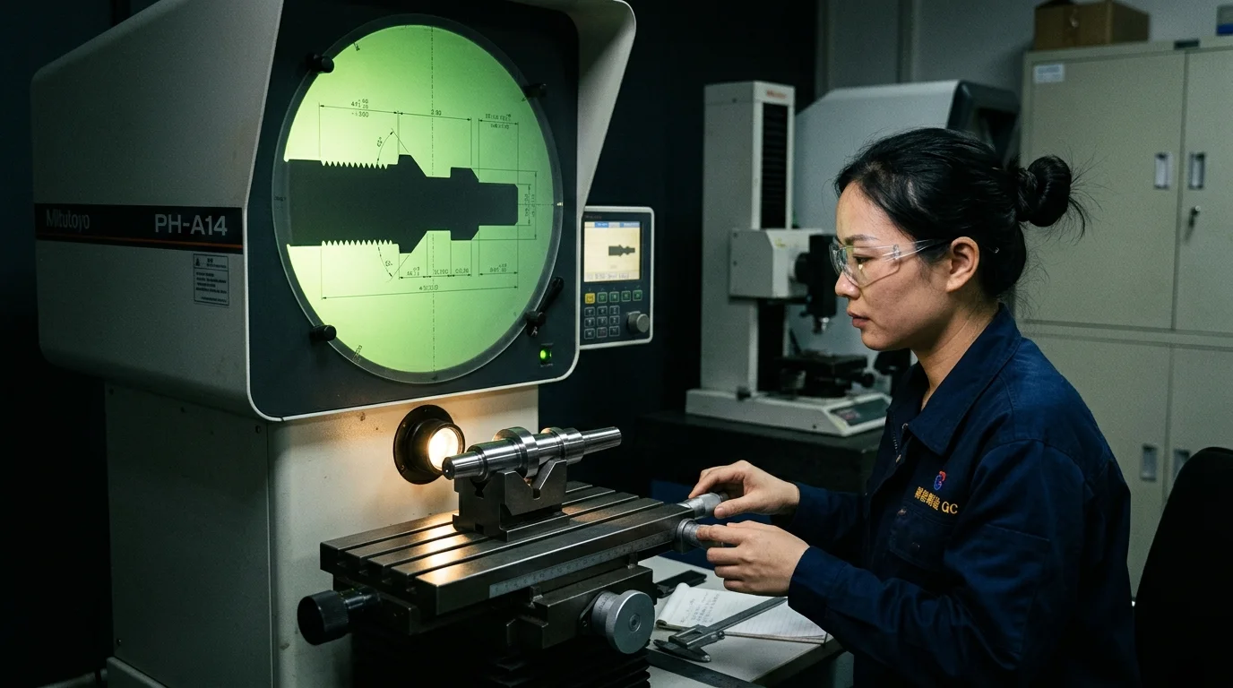
| Optical Measuring Projector / Vision System | 0.001 mm (0.00005 in) | ±0.002 mm | ±0.010 mm (0.02 mm zone) | Complex 2D profiles, thread pitches, micro-chamfers, delicate deburred edges |
| Coordinate Measuring Machine (Zeiss / Mitutoyo CMM) | 0.0001 mm (0.1 µm) | 1.2 µm + L/350 | ±0.005 mm (0.01 mm zone) | Complete 3D GD&T verification, true position, perpendicularity, profile of a surface |
| Pneumatic Air Gauging | 0.0005 mm (0.5 µm) | ±0.0005 mm | ±0.002 mm (0.004 mm zone) | High-volume serial production checking of bore roundness, taper, and diameter |
Quality Documentation & FAI Certification
In mission-critical industries, physical verification must be backed by traceable metrology records. A comprehensive precision quality assurance system includes:
- First Article Inspection (FAI) Report per AS9102: Full 100% ballooned inspection of all drawing dimensions on initial production units prior to full batch sign-off.
- Production Part Approval Process (PPAP Level 3): Rigorous automotive-grade documentation incorporating Process FMEA, Control Plans, Gage R&R studies, and dimensional inspection results.
- Material Test Reports (3.1 MTR / Mill Certs): Verifying chemical composition, tensile strength, and heat-treatment temper.
CNMP Precision Machining & Tolerance Capabilities
As an ISO 9001 and IATF 16949 certified manufacturing partner, CNMP delivers high-precision subtractive CNC manufacturing solutions tailored to the exacting requirements of hardware engineers and global tier-1 supply chains.
- Standard Default Baseline: Automated production executed to ISO 2768-m (medium) and ISO 2768-f (fine) general tolerance standards.
- Achievable Tight Tolerances: Routine production holding ±0.010 mm on turned shafts and 5-axis milled prismatic geometries.
- Micro-Precision Premium Capability: Select Critical-to-Quality features machined down to ±0.005 mm (5 microns / ±0.0002 in) in temperature-controlled 20.0°C machining centers supported by dedicated Zeiss CMM verification.
- Tier-1 Automotive OEM Credentials: Real manufacturing experience delivering high-precision pneumatic air suspension valve blocks for Arnott and leak-free fluid transfer connectors for Dytech, meeting strict APQP and zero-defect automotive cleanliness standards.
- Batch Flexibility: Rapid functional prototyping from MOQ = 1 piece with fast 3–5 day turnaround, seamlessly scaling to low-volume bridge production (10–1,000 pieces) and high-volume serial manufacturing.
When preparing your technical drawing package, our engineering team provides comprehensive Design for Manufacturability (DFM) reviews to identify over-toleranced features and optimize your production costs. Contact our applications team to request a precision CNC machining quote with 24-hour engineering feedback.
Frequently Asked Questions (FAQ)
What is the standard default tolerance for CNC machining?
When no specific numerical tolerance or GD&T callout is annotated on a drawing dimension, the universal standard default for precision CNC machining is ISO 2768-m (Medium). For typical linear dimensions between 6 mm and 30 mm, ISO 2768-m permits a deviation of ±0.20 mm. Modern CNC machining facilities routinely operate to an internal shop baseline of ±0.050 mm (±0.002 in) to ±0.100 mm (±0.004 in) for general metal components.
How does temperature affect CNC machining tolerances?
Workpiece materials expand and contract with temperature according to their Coefficient of Thermal Expansion (Δ L = α × L_0 × Δ T). For example, 6061 aluminum expands by 23.1 µm per meter per degree Celsius. A minor shop floor temperature shift of 5.0°C expands a 100 mm aluminum part by 11.5 µm, which completely exceeds a ±0.005 mm tolerance zone. Extreme precision machining requires temperature-controlled enclosures stabilized at 20.0°C and thermal soaking prior to inspection.
Why can’t engineering plastics hold tight tolerances like metals?
Engineering thermoplastics like POM (Delrin), Nylon, and PTFE exhibit coefficients of thermal expansion 4 to 10 times higher than steels, causing significant size shifts with minor temperature changes. Furthermore, plastics possess lower elastic moduli, causing them to deflect under mechanical vise clamping pressure and cutting forces. Softer plastics like Nylon are also hygroscopic, absorbing atmospheric moisture and expanding up to 2% in volume. Realistic plastic machining tolerances range from ±0.050 mm to ±0.150 mm.
What is the difference between ISO 2768-m and ISO 2768-f?
ISO 2768-1 defines standardized linear and angular tolerances across four classes: f (Fine) and m (Medium). Class f enforces roughly half the permissible deviation of Class m. For example, on a dimension between 6 mm and 30 mm, Class f mandates ±0.10 mm while Class m permits ±0.20 mm. Class m is the global commercial baseline, while Class f is specified for precision instrumentation and tight-fitting assemblies.
How does surface roughness (Ra) impact tolerance verification?
Surface roughness and dimensional tolerance cannot be isolated. An Ra 3.2 μm milled surface possesses micro-peaks and valleys (R_z) spanning 13 to 18 µm. Specifying a ±0.005 mm (10 µm total) tolerance on such a face is impossible to verify because surface roughness irregularities exceed the tolerance band. As an engineering standard, surface roughness (Ra) should never exceed 10% to 20% of the total tolerance zone (Ra ≤ 0.1 to 0.2 × T).
When is a ±0.005mm tolerance actually necessary?
A ±0.005 mm (5 micron / ±0.0002 in) tolerance should be specified only on Critical-to-Quality (CTQ) features where assembly physics strictly demands it. Typical applications include high-speed anti-friction ball bearing journals (H7/h6 or H7/p6 fits), sliding hydraulic spool valve bores, precision alignment dowel sleeves, and sealing faces operating under ultra-high vacuum or high pneumatic pressure. Applying this tolerance to non-mating cosmetic faces unnecessarily multiplies part cost by 3x to 4x.