In precision mechanical engineering and subtractive manufacturing, surface finish is frequently misunderstood as a purely aesthetic consideration. In reality, the surface topography of a machined component directly dictates critical mechanical phenomena: dynamic friction coefficients, hydrodynamic lubrication regimes, fatigue crack nucleation resistance, hermetic seal integrity in high-pressure fluidics, and micro-wear rates in interference assemblies.
Furthermore, secondary surface treatments introduce physical layer growth or substrate etching that alters finished dimensions. Failing to account for plating thickness or anodizing build-up creates an engineering failure mode known on the shop floor as the “Tolerance Trap”—where an in-spec machined part becomes out-of-spec after surface finishing.
Whether procuring high-precision aerospace manifolds or specifying custom CNC machining services for industrial automation, design engineers must navigate the trade-offs between surface roughness parameters (Ra, Rz, RMS), manufacturing cycle times, and coating pre-compensation formulas. Specifying an unnecessarily fine finish can multiply machining cycle times and secondary finishing costs by three- to five-fold. Conversely, under-specifying surface texture can lead to premature seal failure, galling under cyclic loads, and catastrophic assembly seizure.
At-a-Glance: CNC Surface Finish & Roughness Capability Matrix
| Finish Classification | Roughness Range (Ra) | Typical Manufacturing Processes | Mechanical & Functional Role | Dimensional Impact & Coating Growth | Relative Cost Multiplier |
|---|---|---|---|---|---|
| Rough / Secondary Machined | 6.3 to 12.5 µm (250–500 µin) | Heavy rough milling, rough turning | Clearance surfaces, structural brackets, non-contact internal cavities | Zero dimensional addition | 0.8x – 0.9x |
| Standard As-Machined | 1.6 to 3.2 µm (63–125 µin) | Standard 3-axis CNC milling, finish turning | Industrial default baseline; bolted joint mating faces, non-critical brackets | Zero dimensional addition | 1.0x (Baseline) |
| Fine Machined / Turned | 0.8 to 1.6 µm (32–63 µin) | Fine face milling, carbide finish turning, reaming | Static O-ring seals, sliding guideways, precision reference locating faces | Zero dimensional addition | 1.2x – 1.4x |
| Precision Ground / Lapped | 0.1 to 0.4 µm (4–16 µin) | Cylindrical grinding, surface grinding, diamond honing | Dynamic hydraulic spools, high-pressure piston seals, bearing journals | Zero addition (material removed via micro-abrasion) | 2.5x – 4.0x |
| Bead Blasted (#120 Glass) | 1.0 to 1.6 µm (40–63 µin) | Automated / manual abrasive pressure blasting | Uniform non-directional matte texture; eliminates tool marks; glare reduction | Removes 2–5 µm; rounds razor edges; bores require masking | 1.2x – 1.3x |
| Type II Anodizing (Sulfuric) | Retains or slightly increases substrate Ra | Electrolytic sulfuric acid bath (10–25 µm coating) | Corrosion resistance, cosmetic dyeing, mild electrical insulation | +5 to +12 µm per surface outward build (ΔDext = +10–24 µm) | 1.3x – 1.5x |
| Type III Hardcoat Anodizing | Increases substrate Ra by 0.2–0.5 µm | Low-temp sulfuric acid bath (50 µm coating) | Extreme wear resistance (60–70 HRC), thermal barrier, marine corrosion | +25 µm per surface outward build; shrinks internal bores by 50 µm | 1.6x – 2.2x |
| Electroless Nickel (ENP) | Perfectlys replicates underlying substrate Ra | Autocatalytic chemical reduction bath (5–25 µm) | 100% uniform corrosion protection; blind cavities and internal threads | +5 to +25 µm per surface outward build; zero corner dog-boning | 1.5x – 2.0x |
What Is Surface Roughness in CNC Machining? Ra, Rz, RMS & ISO Grades
Surface finish—technically designated as surface texture under ASME B46.1 and ISO 4287—is the complete three-dimensional geometric profile of a real solid surface. It comprises three distinct spatial frequency components:
- Roughness (Micro-roughness): Fine, short-wavelength irregularities produced by cutting tool insert geometry, shearing dynamics, chip formation, and machine tool chatter.
- Waviness (Macro-roughness): Medium-wavelength periodic undulations caused by machine spindle runout, thermal deflection, structural resonance, or workholding workpiece flexing.
- Lay: The predominant geometric direction or orientation of the cutting tool pattern (e.g., parallel, perpendicular, circular, radial, or non-directional).
Deconstructing the Primary Roughness Parameters: Ra, Rz, and RMS
Engineers routinely over-rely on a single parameter: Ra. While Ra is the universal benchmark, relying solely on it can disguise micro-topographical defects that destroy functional assemblies.
1. Ra (Roughness Average / CLA)
Ra (Roughness Average, historically known as Center Line Average or CLA) is the arithmetical mean deviation of the absolute profile values (y) along the evaluation sampling length (L):
Ra = (1 / L) ∫ |y(x)| dx
- Strengths: Universal global benchmark; readily measured by low-cost shop-floor stylus profilometers; effective for tracking general process stability across high-volume production.
- Limitations: Ra is mathematically blind to the shape of surface peaks and valleys. A surface composed of sharp, gouging peaks and narrow valleys can share the exact same mathematical Ra value as a plateau-honed bearing surface composed of wide bearing plateaus and microscopic oil-retaining valleys.
2. Rz (Mean Peak-to-Valley Roughness)
Rz evaluates the average vertical distance between the highest peaks and deepest valleys within individual sampling lengths. Under ISO 4287, Rz represents the mean of the peak-to-valley heights across 5 consecutive cutoff sampling lengths (lr):
Rz = (1 / 5) ∑ [R_pi + R_vi]
Engineering Criticality: In pneumatic valve blocks, hydraulic spool cylinders, and dynamic elastomeric seal interfaces, Rz is drastically more critical than Ra. On a standard CNC milled surface, Rz typically measures 4 to 7 times Ra. If an engineer specifies Ra 3.2 µm for a dynamic hydraulic cylinder, the actual peak-to-valley micro-gouges (Rz) can exceed 18 to 22 µm. These micro-peaks act as microscopic saw blades, abrading nitrile and Viton O-rings within thousands of operating cycles, resulting in premature pressure blowout.
3. RMS (Rq, Root Mean Square Roughness)
Rq (or RMS) is the statistical root mean square of the profile departures from the centerline:
Rq = √[ (1 / L) ∫ y²(x) dx ]
Because deviations are squared prior to averaging, RMS gives significantly higher mathematical weight to extreme isolated peaks and deep fissures. For Gaussian (randomly distributed) machined surfaces, RMS typically approximates RMS ≈ 1.11 × Ra.
4. ISO Roughness Grade Numbers (N-Scale per ISO 1302)
European engineering drawings and heritage documentation frequently express surface texture via standardized ISO Grade Numbers from N1 to N12. Each step along the N-scale represents a doubling of roughness.
Master Roughness Conversion Chart: ISO Grades, Ra, Rz, RMS & Manufacturing Limits
| ISO Grade | Ra (µm) | Ra (µin) | Rz (µm) (Approx.) | RMS (µin) (Approx.) | Typical Manufacturing Process Producing Finish | Typical Engineering Application |
|---|---|---|---|---|---|---|
| N12 | 50.0 | 2000 | 200–300 | 2220 | Flame cutting, rough bandsaw, sand casting | Rough structural stock, non-functional clearance |
| N11 | 25.0 | 1000 | 100–150 | 1110 | Heavy rough planing, deep rough milling | Non-mating mounting plates, clearance channels |
| N10 | 12.5 | 500 | 50–80 | 555 | Heavy rough turning, rough end milling | Welded assemblies, rough fixturing bases |
| N9 | 6.3 | 250 | 25–40 | 280 | Standard rough milling, high-feed turning | Bolted flanges with heavy elastomer gaskets |
| N8 | 3.2 | 125 | 13–22 | 140 | Standard CNC face milling, finish turning | Universal industrial default; general structural parts |
| N7 | 1.6 | 63 | 6.5–11 | 70 | High-speed finish milling, reaming, broaching | Static O-ring faces, precision locating pins |
| N6 | 0.8 | 32 | 3.2–5.5 | 35 | Fine CNC diamond turning, precision reaming | Dynamic sliding fits, bearing housings, hydraulic bores |
| N5 | 0.4 | 16 | 1.6–2.8 | 18 | Cylindrical / surface grinding, fine honing | High-pressure hydraulic valve spools, journal bearings |
| N4 | 0.2 | 8 | 0.8–1.5 | 9 | Precision cylindrical grinding, micro-honing | Aircraft landing gear shock pistons, engine cam lobes |
| N3 | 0.1 | 4 | 0.4–0.8 | 4.5 | Lapping, fine diamond burnishing, superfinishing | Mechanical face seals, precision metrology reference surfaces |
| N2 | 0.05 | 2 | 0.2–0.4 | 2.2 | Precision optical lapping, chemical-mechanical polish | Laser mirror substrates, semiconductor vacuum wafer seals |
| N1 | 0.025 | 1 | 0.1–0.2 | 1.1 | Ultra-precision diamond turning (SPDT) | Infrared optical lenses, laser resonator mirrors |
Standard As-Machined CNC Surface Roughness by Process
Achieving a specific target surface roughness directly from subtractive cutting tools depends upon cutting kinematics, tooling geometry, feed rates, workpiece rigidity, and chip dynamics. When commissioning precision CNC milling services or turned components, understanding toolpath mechanics prevents unrealistic drawing specifications.
1. CNC Turning Kinematics & Theoretical Roughness
In single-point CNC lathe turning, the tool nose radius (rε) traces a continuous helical path along the rotating workpiece. This geometry creates theoretical cusp heights (scallops) between successive feed revolutions. The theoretical peak-to-valley height (htheory) and arithmetic average roughness (Ratheory) are calculated using:
h_theory ≈ f² / (8 × r_ε) | Ra_theory ≈ [f² / (32 × r_ε)] × 1000 (in µm)
- Where f is the feed rate in millimeters per revolution (mm/rev).
- rε is the tool nose insert corner radius in millimeters (mm).
Engineering Takeaway: Roughness scales with the square of the feed rate (f²). Halving the feed rate decreases theoretical roughness by a factor of 4. Conversely, increasing the tool nose radius from 0.4 mm to 0.8 mm cuts roughness in half for identical feed rates.
In actual production turning, real-world Ra is roughly 1.5 to 2.0 × Ratheory due to material side-flow, built-up edge (BUE) formation, and spindle micro-vibration. Standard finish turning reliably delivers Ra 0.8 to 1.6 µm (32–63 µin) without requiring secondary grinding operations per our precision CNC turning services.
2. CNC Milling Kinematics: Face Milling vs. End Milling
- Face Milling: Large-diameter cutter bodies sweeping across broad planar surfaces produce intersecting arc-sweep cross-hatch marks. Wiper inserts (inserts with flat ground secondary cutting edges) are routinely installed in face mills to burnish tool scallops, dropping face-milled finishes down to Ra 0.4 to 0.8 µm.
- Peripheral End Milling: The side flutes of an end mill sweep across vertical walls. Flute deflection, tool runout, and chip re-cutting typically yield finishes of Ra 1.6 to 3.2 µm.
- 3D Ball-Nose Scallop Surfacing: When generating complex organic contours on multi-axis machining centers, stepover distance (ae) dictates the cusp height (
h_cusp ≈ a_e² / [8 × R]). Tight stepovers produce smooth transitions (Ra 1.6 µm) but drastically extend cycle times.
3. Precision Grinding, Lapping, and Wire EDM
- Surface and Cylindrical Grinding: Employs bonded aluminum oxide, silicon carbide, or CBN abrasive wheels. Micro-grit cutting edges shear microscopic ribbons of metal, routinely achieving Ra 0.2 to 0.4 µm (8–16 µin) on hardened steels (> 50 HRC).
- Wire EDM (Electrical Discharge Machining): Non-contact thermal erosion removes material via microscopic electrical spark discharges. Wire EDM creates a multi-directional, matte-sparked recast layer with Ra 0.8 to 2.5 µm. Modern multi-pass (skim-cut) wire EDM can achieve finishes as fine as Ra 0.4 µm.
- Lapping & Polishing: Loose diamond or aluminum oxide slurries between cast-iron laps eliminate residual machine marks, achieving sub-micron flatness and finishes down to Ra < 0.05 µm (2 µin).
Mechanical Surface Finishing Processes: Texture, Deburring & Friction Control
Secondary mechanical finishes modify surface topography without applying chemical immersion or electrolytic coatings. These processes alter surface hardness, remove tool marks, or produce matte textures.
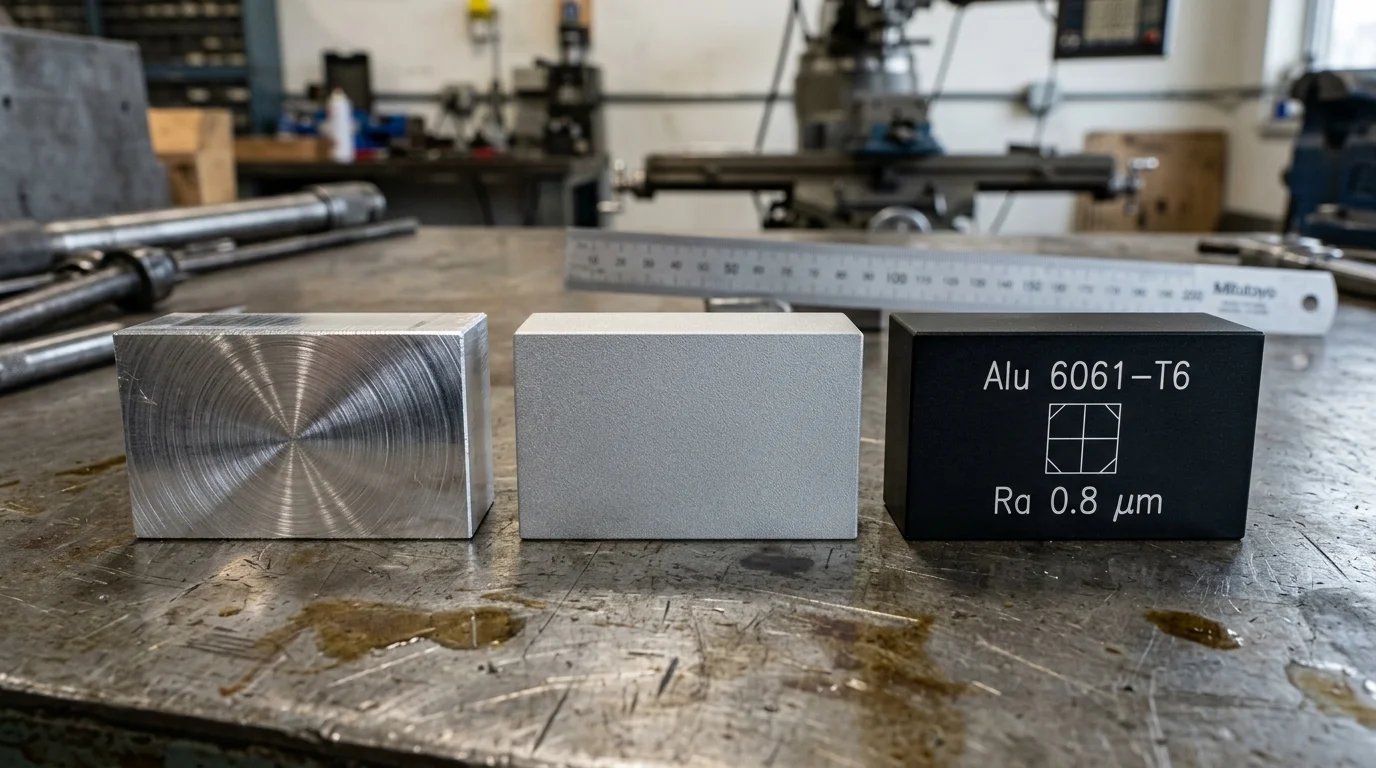
1. As-Machined (Standard / Mill Finish)
- Characteristics: Untreated physical surface containing visible toolpaths, cutter sweep marks, and microscopic burrs along sharp edges.
- Surface Roughness: Ra 1.6 to 3.2 µm (63–125 µin).
- Advantages: Zero secondary labor cost; immediate turn-around; 100% preservation of machined dimensional tolerances.
- Limitations: Aesthetic tool marks remain visible; directional cutter marks can impede dynamic sealing; edge burrs require manual deburring.
2. Bead Blasting (Glass Bead & Aluminum Oxide)
Bead blasting subjects the component to a high-velocity stream of fine spherical or angular abrasive media propelled by compressed air.
- Glass Bead Blasting (#100 to #170 Mesh): Spherical soda-lime glass beads peen the metallic surface, cold-working the outer layer and producing an attractive, satin-matte non-directional texture (Ra 1.0 to 1.6 µm).
- Aluminum Oxide Blasting (#80 to #120 Mesh): Angular corundum particles etch the surface, creating a sharp micro-anchor tooth pattern (Ra 2.0 to 3.5 µm) specifically engineered for priming paint and powder-coat adhesion.
- The Masking Warning: Bead blasting physically removes 2 to 5 µm of base material and dulls precision sharp corners. Crucially: precision bearing bores, slip-fit dowel holes, and internal threads MUST be masked with silicone plugs prior to blasting. Leaving high-precision bores unmasked will blow out roundness tolerances and ruin bearing press fits.
3. Mechanical Polishing & Buffing
- Staged Abrasive Polishing: Involves progressive sequential passes with emery cloth and silicon carbide papers (from #320 grit through #800 and #1500 grit), followed by rotating cotton buffing wheels charged with diamond paste.
- Achievable Roughness: Optical mirror polish achieves Ra 0.05 to 0.1 µm (2–4 µin).
- Applications: Food processing sanitary machinery (eliminating bacteria harboring pits per 3-A Sanitary Standards), optical reflector housings, and semiconductor ultra-high-vacuum (UHV) chambers.
4. Rotary Tumbling / Vibratory Deburring
Ceramic or plastic media in vibratory bowls radius sharp edges, peen burrs, and blend minor cutter marks across high-volume production batches. Yields an even, low-cost satin finish (Ra 0.8 to 1.6 µm).
Anodizing Aluminum: Type II vs. Type III Hardcoat & “The Tolerance Trap”
Anodizing is an electrolytic passivation process that converts the surface of aluminum alloys into an extremely hard, corrosion-resistant aluminum oxide (Al2O3) ceramic matrix. Unlike electroplating—which only adds material on top of the substrate—anodizing grows from the aluminum itself.
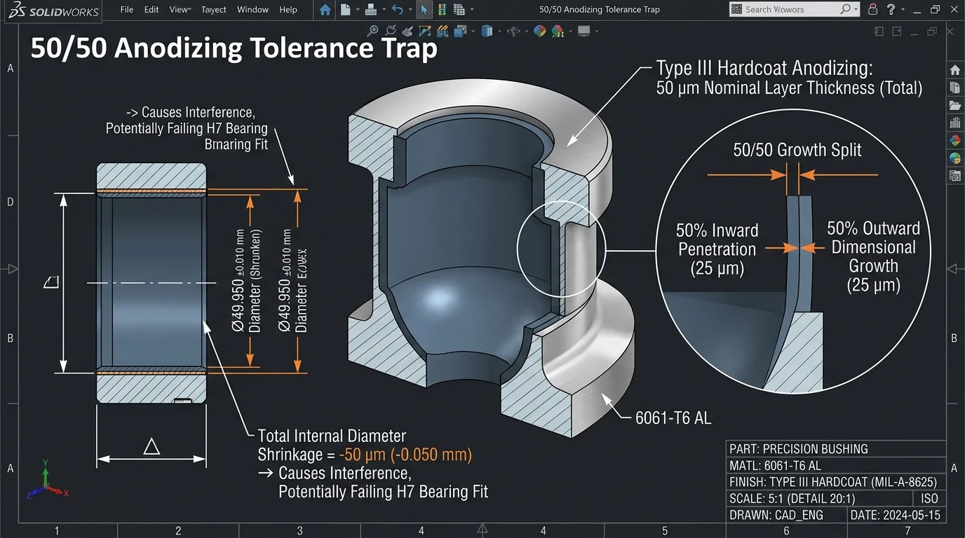
The 50/50 Growth & Penetration Rule
Anodizing builds inward and outward in equal proportions:
- 50% of the coating thickness penetrates into the base aluminum substrate.
- 50% of the coating thickness builds outward from the original machined boundary.
Understanding this physical mechanism is vital for calculating post-coating dimensions. For any external feature (such as an outside diameter or block thickness), the total dimensional growth is:
ΔD_external = +2 × (Outward Growth) = +1 × (Total Coating Thickness)
Conversely, for an internal cylindrical bore or pocket, the outward growth pushes toward the center axis, shrinking the bore diameter:
ΔD_internal = -2 × (Outward Growth) = -1 × (Total Coating Thickness)
Type II Sulfuric Anodizing vs. Type III Hardcoat Anodizing (MIL-A-8625)
| Parameter / Specification | Type II Sulfuric Acid Anodizing (MIL-A-8625 Type II) | Type III Hardcoat Anodizing (MIL-A-8625 Type III) |
|---|---|---|
| Primary Engineering Purpose | Aesthetic coloration, basic atmospheric corrosion resistance, light wear protection | Extreme abrasive wear resistance, high dielectric strength, severe marine environment protection |
| Bath Chemistry & Temperature | 15–20% H2SO4 electrolyte; room temperature (20°C / 68°F) | Low-temperature sulfuric acid (0 to 5°C / 32–41°F); high current density (20–36 A/ft²) |
| Standard Total Coating Thickness | 10 to 25 µm (0.0004 to 0.0010 in) | 50 µm ± 10 µm (0.0020 in ± 0.0004 in) |
| Outward Dimensional Growth (Per Surface) | +5 to +12 µm (+0.0002 to +0.0005 in) | +25 µm (+0.0010 in) |
| Impact on External Diameter (ΔDext) | +10 to +24 µm (+0.0004 to +0.0010 in) | +50 µm (+0.0020 in) |
| Impact on Internal Bore (ΔDint) | -10 to -24 µm (Shrinks) | -50 µm (Shrinks by full 0.050 mm!) |
| Surface Hardness | 300 to 400 HV (Micro-hardness) | 60 to 70 HRC equivalent (500 to 650 HV), comparable to hardened case tool steel |
| Surface Roughness Impact | Negligible change on fine machined surfaces (Ra Δ < 0.1 µm) | Roughens surface; increases Ra by 0.2 to 0.5 µm (8–20 µin) |
| Color & Dye Capabilities | Vivid colors (Black, Clear, Red, Blue, Gold, Green) | Naturally dark bronze, charcoal grey, or dyed black only |
The Tolerance Trap: Real-World Engineering Failure Scenario
Consider an aluminum fluid pump housing designed to seat an ISO standard deep-groove ball bearing (6004):
- Nominal Bearing Outside Diameter: 42.000 mm.
- Specified Bearing Bore Tolerance: Ø42.000 +0.016/-0.000 mm (ISO H7 fit).
The Catastrophic Sequence:
- The CNC programmer mills the bore precisely to 42.008 mm (dead center of the H7 tolerance band).
- The print calls out:
"Hardcoat Anodize per MIL-A-8625 Type III Class 1, 50 µm thickness". - The parts go directly into the anodizing tank without bore masking or pre-machining compensation.
- Anodizing creates 25 µm of outward oxide growth on every surface. Across the diametral cylinder, this shrinks the bore by 2 × 25 µm = 50 µm (0.050 mm).
- The post-anodize bore measures 41.958 mm. The H7 bearing seat is undersized by 0.042 mm, completely seizing the bearing and scrapping an expensive multi-axis component.
The Engineering Solutions:
- Solution A (Pre-Machining Offset): The machinist must cut the internal bore oversize to 42.058 mm before sending it to the anodizer, so that after 50 µm shrinkage, it lands perfectly at 42.008 mm.
- Solution B (Selective Masking): Call out on the 2D drawing:
"MASK BORE Ø42.008 FROM HARDCOAT ANODIZE". The finishing facility applies custom silicone plugs or liquid lacquer prior to immersion.
Chemical Film / Alodine / Chromate Conversion (MIL-DTL-5541)
When electrical conductivity or RF grounding is required alongside corrosion protection, Chemical Film (Alodine / Iridite per MIL-DTL-5541 Type II Class 3) is the preferred choice. Coating thickness is sub-microscopic (< 1 µm). Dimensional change is mathematically zero. It preserves 100% of underlying machined dimensions and maintains electrical continuity across grounding bosses.

Plating & Chemical Conversion: Uniformity, Threads & Corrosion Protection
1. Electroless Nickel Plating (ENP per MIL-C-26074 / ASTM B733)
Electroless Nickel Plating (ENP) represents the premier technical coating for precision mechanical components requiring extreme wear and corrosion resistance across intricate geometries. Unlike electrolytic plating, ENP does not use an external electrical power supply. Material deposition occurs via an autocatalytic chemical reduction of nickel and hypophosphite ions in an aqueous bath.
- 100% Uniform Deposition (No “Dog-Bone” Edge Build-Up): In electrolytic plating, electric field flux concentrates on sharp exterior corners, ridges, and thread crowns, causing coatings to deposit 200% to 300% thicker on edges than in recesses (the dog-bone defect). In contrast, ENP deposits with absolute micron-level uniformity across internal blind holes, tapped threads, cross-drilled fluid galleries, and complex gear teeth.
- Coating Thickness Control: Standard engineering specifications range from 5 µm (flash rust inhibitor), 12 to 25 µm (standard industrial wear), to 50 µm (extreme chemical resistance). Outward growth is 100% additive per surface.
- Hardness: Delivers 48–52 HRC as-plated, and can be post-bake heat-treated (400°C for 1 hour) to reach 68–70 HRC, matching hard chrome plating without environmental toxicity.
2. Zinc Plating & Electroplating (ASTM B633)
Zinc plating offers economical sacrificial cathodic corrosion protection for alloy steels per our CNC machining materials selection guide. However, because electroplated zinc accumulates excessively on external male thread crests, standard threads (e.g., M6x1.0 Class 6g) will fail GO/NOGO thread gauge checks after plating unless cut with special undercut pitch diameters (Class 6e or 6d) prior to plating.
3. Stainless Steel Passivation (ASTM A967 / AMS 2700)
Passivation is an acid bath (nitric or citric acid) that chemically dissolves microscopic free iron smeared onto the surface by cutting tool inserts. It rapidly accelerates the formation of a continuous, chemically passive chromium oxide (Cr2O3) barrier layer. It causes zero measurable dimensional change and does not alter surface roughness.
4. Black Oxide (MIL-DTL-13924)
A chemical conversion coating for carbon and alloy steels that converts surface iron into magnetite (Fe3O4). Layer thickness is less than 1 µm (0.00004 in), causing negligible dimensional impact. It retains sharp edges and precision bore dimensions, requiring protective oil impregnation to prevent rusting.
Master Surface Treatment & Coating Specification Matrix
| Surface Treatment | Typical Military / Industrial Spec | Primary Substrates | Thickness Range (µm) | Outward Growth Per Face (µm) | Internal Bore Delta (ΔDint) | Surface Roughness Change (ΔRa) | Corrosion Salt Spray (ASTM B117) | Electrical Conductivity |
|---|---|---|---|---|---|---|---|---|
| As-Machined | N/A | All Metals & Plastics | 0 | 0 | 0 | Baseline (1.6–3.2 µm) | Substrate dependent | High (Metals) |
| Bead Blast (#120 Glass) | Standard Shop Spec | All Metals | Removes 2–5 | -2 to -5 | Enlarges +4 to +10 µm | Ra → 1.0–1.6 µm | Substrate dependent | High |
| Passivation | ASTM A967 / AMS 2700 | 300 / 400 / 17-4PH SS | 0 (Molecular) | 0 | 0 | Zero change | > 100–500 hrs | High |
| Black Oxide | MIL-DTL-13924 | Carbon / Alloy Steel | 0.5 to 1.5 | +0.5 | Negligible (-1 µm) | Zero change | < 24–96 hrs (with oil) | High |
| Alodine / Chem Film | MIL-DTL-5541 Class 3 | Aluminum Alloys | 0.2 to 0.8 | < +0.5 | Negligible | Zero change | > 168 hrs | Electrically Conductive |
| Type II Anodize | MIL-A-8625 Type II | Aluminum Alloys | 10 to 25 | +5 to +12 | Shrinks -10 to -24 µm | Minimal (ΔRa < 0.1 µm) | > 336 hrs | Non-conductive insulator |
| Type III Hardcoat | MIL-A-8625 Type III | Aluminum Alloys | 50 ± 10 | +25 ± 5 | Shrinks -50 ± 10 µm | Roughens (ΔRa +0.3 µm) | > 1000 hrs | High Dielectric Breakdown |
| Electroless Nickel | MIL-C-26074 / ASTM B733 | Steel, Alum, Copper | 5 to 25 | +5 to +25 | Shrinks -10 to -50 µm | Replicates substrate | > 500–1000 hrs | Mildly Conductive |
| Powder Coating | Commercial Spec | Steels, Aluminum | 60 to 100 | +60 to +100 | Shrinks -120 to -200 µm | Forms smooth orange-peel | > 1000 hrs | Insulator |
How to Specify Surface Finishes on Technical Drawings: 5 Engineering Rules
Vague or conflicting drawing callouts are the primary cause of quotation delays, machining disputes, and scrapped parts. Follow these 5 proven rules per ASME Y14.36M and ISO 1302:
Rule 1: Specify a Sensible Default in the Title Block
Never leave surface finish unstated. Conversely, never apply an ultra-fine blanket callout across the entire drawing. Include a standard general note in the drawing title block:
“ALL MACHINED SURFACES Ra 3.2 µm (125 µin) UNLESS OTHERWISE SPECIFIED.”
Reserve fine callouts (Ra 0.8 µm or ground Ra 0.4 µm) strictly for local functional features, pointing directly to bearing seats, sliding ways, or dynamic O-ring grooves. Review finishing cost impacts in our CNC machining cost breakdown.
Rule 2: Explicitly Define the Coating Application Boundary
Because anodizing, plating, and powder coating add physical material, technical drawings must define whether dimensions apply before or after surface finishing:
- Option A:
"ALL DIMENSIONS APPLY AFTER SURFACE FINISH AND PLATING."(Recommended: the manufacturing supplier is fully responsible for calculating pre-machining compensation offsets). - Option B:
"ALL DIMENSIONS APPLY BEFORE SURFACE TREATMENT."(Common in aerospace: machining houses inspect raw metal dimensions; subsequent chemical platers are verified via coupon test samples).
Rule 3: Call Out Masking Zones and Non-Plated Features
If your component requires both wear-resistant Hardcoat anodizing on sliding exterior faces and tight H7 bearing fits on internal bores, explicitly indicate masked regions:
“SURFACE TREATMENT: MIL-A-8625 TYPE III HARDCOAT CLASS 1. BORES Ø25.000 +0.012/-0.000 AND TAPPED HOLES M6x1.0 MUST BE MASKED AND FREE FROM ANODIZE.”
Rule 4: Specify Oversize Taps for Plated Threads
When steel or aluminum parts receive Electroless Nickel or electroplated zinc thicker than 8 µm, standard internal threads will bind when mating with standard 6g fasteners. Specify pre-plate oversize thread tapping:
“INTERNAL THREADS TO BE TAPPED WITH OVERSIZE 6G/6AX TAP PRIOR TO PLATING TO ENSURE 6H FIT AFTER PLATING.”
Rule 5: State Roughness Cutoff Wavelength (λc) for Critical Inspections
Stylus roughness profilometers require an electronic cutoff filter wavelength (λc) to separate micro-roughness from macro-waviness. Per ISO 4288:
- For surfaces Ra 0.1 to 2.0 µm: Cutoff filter is λc = 0.8 mm (sampling length lr = 0.8 mm, total evaluation length L = 5 × 0.8 = 4.0 mm).
- For surfaces Ra 2.0 to 10.0 µm: Cutoff filter is λc = 2.5 mm.
Explicitly adding Ra 0.8 / λc 0.8 to critical seal prints prevents inspection disputes between supplier and receiving metrology labs per our precision quality assurance protocols.
Shop Floor Quality Verification: Profilometers & Metrology
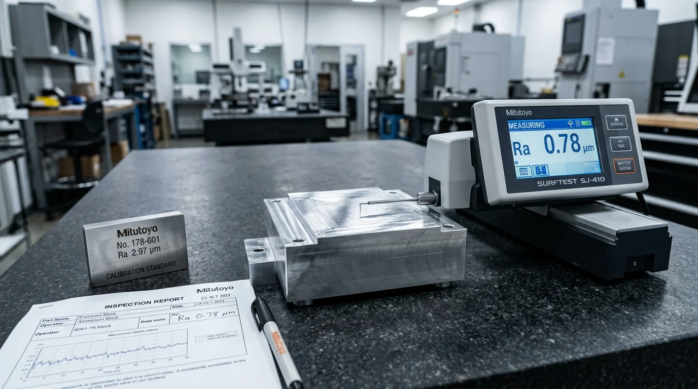
Verifying surface roughness requires calibrated metrology instruments operating inside controlled environments (20°C ± 1°C).
1. Contact Stylus Profilometers (Mitutoyo Surftest / Taylor Hobson)
- A high-precision diamond stylus (typically 2 µm or 5 µm tip radius) traces mechanically across the surface at a constant traverse speed (0.5 mm/sec).
- A differential inductive or piezoelectric transducer converts vertical needle displacement into an electronic waveform.
- Skidded vs. Skidless Probes: Skidded styli rest on a curved metal reference skid sliding alongside the needle (effective for flat planes, but distorts waviness). Skidless probes trace against an internal high-precision glass datum, allowing accurate measurement of stepped shoulders, curvature, and Rz.
2. Optical Metrology & 3D Confocal Profilometry
- Coherence Scanning Interferometry (CSI) & Confocal Microscopy: Utilizes white light interference or scanning lasers to capture complete 3D surface area topographies (Sa, Sz).
- Advantage: 100% non-contact; eliminates risk of diamond stylus scratching soft polished aluminum, optical brass, or polymer medical parts.
Sourcing Precision Surface Finishes with CNMP
Balancing mechanical tolerances with chemical surface conversion requires integrated machining and finishing expertise. At advanced production facilities like CNMP, combining 3-, 4-, and 5-axis CNC milling with in-house certified finishing partnerships guarantees that every component meets rigorous GD&T standards both before and after surface treatment.
From high-precision fluid blocks operating under tight hydraulic tolerances to rapid functional prototypes from MOQ = 1 piece, comprehensive metrology verification—including Mitutoyo surface profilometer inspection, CMM dimensional verification per our CNC machining tolerances guide, and full First Article Inspection (FAI) reports—ensures your parts perform reliably in demanding field environments.
To evaluate your engineering specifications or calculate coating compensation for production batches, explore our full range of surface finishing services or request a precision CNC machining quote with 2D drawings and CAD models today.
Frequently Asked Questions (FAQ)
What is the standard default surface finish for CNC machined parts?
The universal default surface finish for CNC milling and turning is Ra 3.2 µm (125 µin), corresponding to ISO grade N8. This standard “as-machined” finish displays visible tool cutter paths and feed marks but provides an optimal economic balance for structural brackets, housing bodies, and general industrial hardware without incurring secondary polishing, grinding, or extended machining cycle times.
How does surface roughness (Ra) differ from Rz and RMS?
Ra is the mathematical arithmetical average of all profile heights and depths across the assessment length. Rz measures the average height between the 5 highest peaks and 5 deepest valleys, making it roughly 4 to 7 times larger than Ra and far more sensitive to extreme micro-gouges that cause O-ring fluid leaks. RMS (Rq) is the statistical root mean square of roughness, giving roughly 11% higher value than Ra on Gaussian surfaces.
How much dimensional thickness does Hardcoat anodizing add?
Hardcoat anodizing (MIL-A-8625 Type III) typically creates a total coating thickness of 50 µm (0.050 mm / 0.002 in). Because anodizing follows the 50/50 rule—50% substrate penetration and 50% outward build—it adds 25 µm (0.001 in) of outward dimensional growth per surface. This increases external shaft diameters by +50 µm and shrinks internal bore diameters by -50 µm.
Why is Electroless Nickel preferred over standard electroplating for precision threads?
Electroless Nickel Plating (ENP) deposits via an autocatalytic chemical reaction without electrical current, resulting in 100% uniform layer thickness across all internal cavities, cross-holes, and thread profiles. In contrast, electrolytic electroplating concentrates high electrical flux on external thread crests and sharp corners (the “dog-bone effect”), creating excessive build-up that binds threaded fasteners during assembly.
Can bead blasting remove CNC machining tool marks completely?
Yes. Glass bead blasting (#100 to #170 mesh) peens the outer metal surface with spherical particles, effectively blending and erasing light milling cutter sweep marks and turning spirals. It creates a clean, non-reflective satin-matte finish (Ra 1.0 to 1.6 µm). However, deep tool gouges (> 10 µm) or heavy chatter marks must be semi-finished with finer toolpaths prior to blasting, as excessive blasting will alter dimensional tolerances and round off precision edges.
How do I properly call out surface roughness on an engineering drawing?
Under ASME Y14.36M and ISO 1302, use the standard checkmark surface texture symbol with the maximum allowable numerical Ra value placed directly above the horizontal bar (e.g., √0.8). If a specific cutoff filter is required, annotate it alongside (e.g., 0.8 / λc 0.8). Always designate on the drawing whether dimensions apply before or after surface finishing (e.g., "DIMENSIONS APPLY AFTER FINISH").