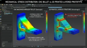
In mechanical engineering and precision hardware development, a 3D CAD model that appears flawless on a computer screen can prove impractical, prohibitively expensive, or physically impossible to manufacture once released to the machine shop floor. Subtractive CNC milling and turning are governed by unyielding mechanical laws: the rotary geometry of spinning cylindrical cutters, the cubic deflection physics of cantilevered tool shanks, cutting force-induced workpiece chatter, and line-of-sight toolpath access.
Design for Manufacturability (DFM) is the engineering discipline of designing component geometry specifically to streamline machining operations, eliminate redundant setups, minimize tool wear, and prevent dimensional non-conformance. Implementing proactive DFM guidelines during early CAD conceptualization routinely reduces machining cycle times by 30% to 60%, eliminates the need for expensive specialized tooling or wire EDM, and ensures that critical functional tolerances can be maintained repeatably.
This comprehensive technical design guide provides mechanical engineers, product designers, and sourcing professionals with actionable geometric rules, mathematical deflection formulas, feature limits, and CAD optimization strategies across modern 3-axis, 4-axis, and 5-axis CNC machining workflows.
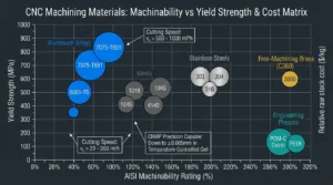
For an economic breakdown of machine hourly rates and batch amortization, consult our companion CNC machining cost guide. To evaluate raw stock selection and machinability ratings, reference our CNC machining materials chart.
1. Core Principles of Design for Manufacturability (DFM) in Subtractive CNC
Unlike additive manufacturing (3D printing), where material is deposited layer-by-layer regardless of interior cavity geometry, CNC machining is strictly subtractive. Solid billets of metal or plastic are cut away by rotating end mills, face mills, drills, and single-point turning inserts.
Every CNC design decision must balance three interrelated physical constraints:
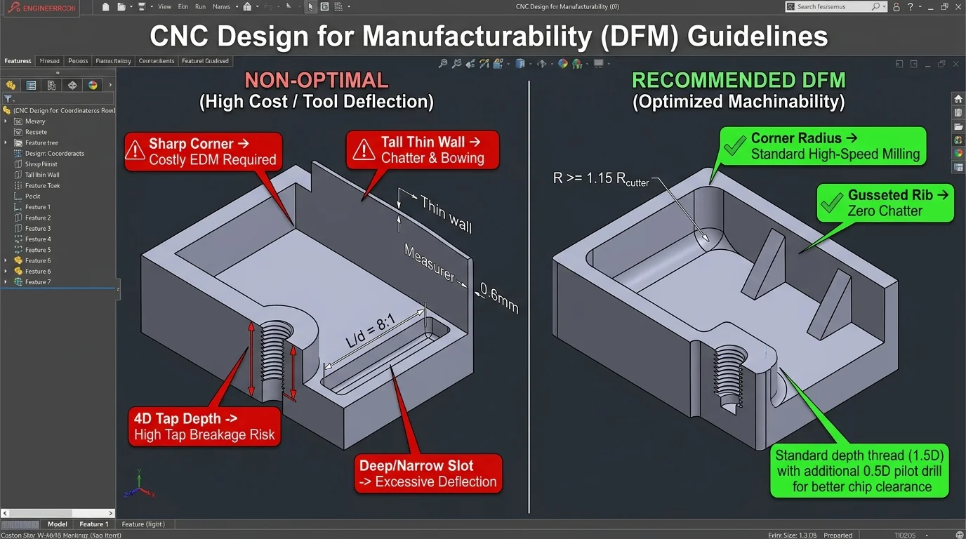
- Tool Rotation Geometry: All rotary cutting tools (end mills, bull-nose cutters, drills, reamers) produce circular cuts. A standard rotating end mill cannot cut a sharp 90° inside vertical corner, nor can a drill bit create a perfectly flat-bottom hole without secondary plunging operations.
- Cantilever Deflection Physics: Every cutting tool overhangs from its machine spindle toolholder as a cantilever beam. As depth increases relative to tool diameter (L/d aspect ratio), tool deflection escalates exponentially with the cube of length (L^3), leading to wall taper, chatter, dimensional drift, and premature tool breakage.
- Workpiece Deflection and Vibration: Unsupported thin walls and tall slender ribs vibrate under cutting shear forces. When workpiece stiffness is insufficient to counteract cutting pressures, regenerative chatter ruins surface roughness, forcing machine operators to throttle feed rates down to fractional velocities.
- Workholding and Setup Accessibility: Every face requiring machining must be accessible by the cutter spindle. If a component features geometric details across six opposing orthogonal faces, a standard 3-axis mill requires six discrete fixture setups, multiplying labor costs and datum stackup errors.
Corner Engagement Comparison: Standard vs Oversized Radii
| Identical Radius (Poor DFM) Rpocket = Rcutter = 6.0 mm |
Oversized Radius (Recommended DFM) Rpocket = 7.0–8.0 mm (Rcutter = 6.0 mm) |
|---|---|
| 180° Full Cutter Wrap Angle: Tool is completely enclosed by material in the 90° corner. | 90° Smooth Interpolation Arc: Tool maintains continuous tangential circular motion. |
| Sudden 300% Cutting Force Spike: Instantaneous surge causes tool deflection and severe chatter. | Constant Radial Chip Load: Cutting force remains stable with zero spike. |
| Forced 70% Feed Rate Drop: CAM program must decelerate or pause to avoid tool fracture. | Sustains High Feed Velocity: Tool navigates the corner at full programmed feed. |
| Tapered Dwell Marks & Rough Surface: Heavy chatter marks require manual bench de-burring. | Pristine Corner Surface Finish: Meets Ra ≤ 0.8 μm without secondary polishing. |
Corner Relief Techniques for Rectangular Mating Inserts
When a milled pocket must house a square mating component (such as an electronic PCB, battery cell, or rectangular alignment key), internal corner radii prevent the square component from seating flush against the pocket walls.
Rather than specifying costly wire EDM to square the corners, deploy corner relief undercuts:
- Dog-Bone Fillet: The cutter extends diagonally past the corner by a distance equal to tool radius, cutting a circular clearance lobe. Both adjacent perpendicular walls remain fully functional reference datums.
- T-Bone Relief: The cutter extends straight along one wall past the corner. This simplifies CAM programming while preserving a continuous reference face on the primary datum wall.
- Drilled Corner Cleats: Small holes are drilled at the four corners prior to pocket milling, clearing the corners completely.
3. Cavity & Pocket Depth Limitations: Deflection vs. Cycle Time
Milling deep interior pockets introduces significant physical challenges related to tool cantilever stiffness and chip evacuation.
Cantilever Beam Mechanics in Milling
A solid carbide end mill held in a spindle toolholder acts as an elastic cantilever beam subjected to radial cutting forces. The deflection (y) at the tool tip is governed by Euler-Bernoulli beam mechanics:
Thin Wall Deflection & Chatter Mechanics
- Cantilever Bending (F → Elastic Wall Deflection): As cutting force F engages an unsupported thin rib, bending deflection scales with the cube of wall height (H3). The top edge flexes away from the tool, creating taper errors.
- Regenerative Harmonic Chatter: The elastic spring-back of the wall synchronizes with cutter tooth pass frequency, causing resonant vibration ripples (Ra > 6.3 μm).
- Yield Point Exceedance: Under aggressive roughing feeds, dynamic cutting pressure permanently deforms the wall beyond its yield strength (Rp0.2), permanently bowing the component.
Minimum Wall Thickness Rules by Material Group
Minimum allowable wall thickness depends directly on the workpiece material’s modulus of elasticity (E), tensile yield strength, and thermal conductivity:
| Material Family | Typical Alloy Grades | Absolute Minimum Wall | Recommended Minimum Wall | Maximum Unsupported Height-to-Thickness Ratio (H/T) |
|---|---|---|---|---|
| Structural Aluminum | 6061-T6, 7075-T651 | 0.8 mm (0.032 in) | ≥ 1.5 mm (0.060 in) | H/T ≤ 6:1 (unsupported); 10:1 with cross-ribs |
| Carbon & Alloy Steels | 1018, 1045, 4140 | 0.8 mm (0.032 in) | ≥ 1.2 mm (0.048 in) | H/T ≤ 8:1 |
| Austenitic Stainless | 304, 316L, 17-4 PH | 1.0 mm (0.040 in) | ≥ 2.0 mm (0.080 in) | H/T ≤ 5:1 (high work-hardening push-off force) |
| Titanium Alloys | Ti-6Al-4V Grade 5 | 1.0 mm (0.040 in) | ≥ 1.8 mm (0.070 in) | H/T ≤ 5:1 (low thermal dissipation) |
| Engineering Plastics | POM-C Delrin, PEEK | 1.5 mm (0.060 in) | ≥ 2.5 mm (0.100 in) | H/T ≤ 3:1 (low modulus E ≈ 3 GPa, high thermal drift) |
| Soft Polymers | PTFE, UHMW-PE | 2.0 mm (0.080 in) | ≥ 3.5 mm (0.140 in) | H/T ≤ 2:1 (prone to cold-flow under clamping) |
DFM Rib Reinforcement Strategies
If your structural or thermal specifications mandate thin cross-sections:
- Incorporate Triangular Gussets: Adding small triangular support gussets at 50 mm intervals along tall walls increases rib bending stiffness by over 400%.
- Step the Wall Thickness: Design walls thicker at the base where bending moments are highest, tapering to a thinner profile at the top edge.
- Box-Enclosure Interlocking: Interconnect intersecting ribs into closed cellular grids (waffle patterns), creating rigid structural loops that cancel out harmonic vibration.
5. Hole & Thread Design Rules: Tapping Limits & Depth Ratios
Holes and threaded fasteners represent the most frequent geometric features on precision machined parts. Incorrect hole dimensions and thread specifications create severe tool breakage risks.
Standard Tooling vs. Custom Hole Sizing
- Always size drilled holes to match standard commercial twist drill diameters (standard fractional inches or metric whole/half millimeters).
- Specifying non-standard diameters (e.g., Ø 7.35 mm) forces the machine shop to order custom ground drills or deploy slow, multi-pass circular end mill interpolation, significantly increasing unit cost.
Hole Depth Aspect Ratio (D/L)
Standard twist drills achieve optimal chip evacuation and dimensional straightness at depths up to:
Maximum Standard Hole Depth ≤ 5 × to 6 × Hole Diameter
Deeper holes (>8× D) require specialized parabolic-flute peck-drilling or dedicated gun-drilling machinery to clear chips and prevent drill wander. When deep holes intersect perpendicular fluid channels, ensure the intersection occurs at a 90° perpendicular axis; entering an angled surface causes drill deflection and catastrophic bit breakage.
The 1.5D to 2D Thread Engagement Rule
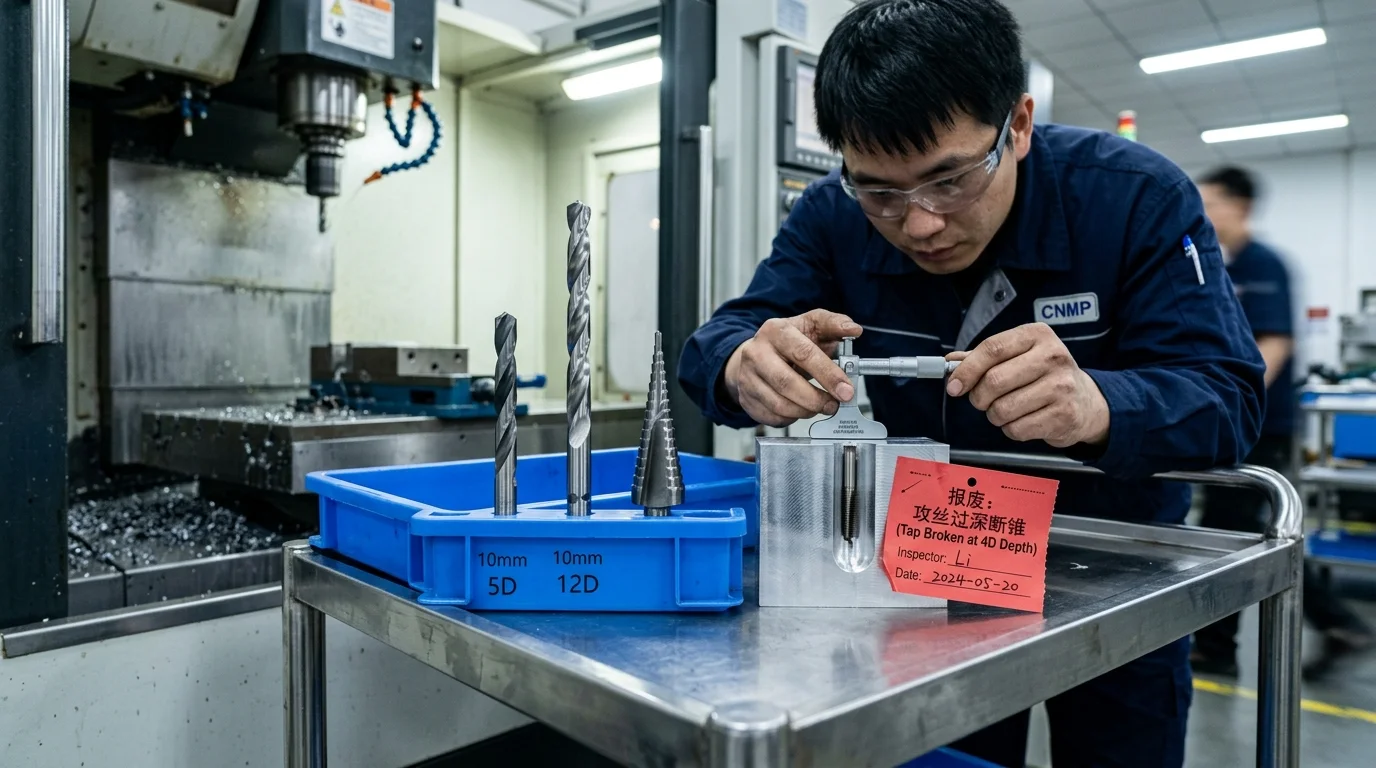
A widespread misconception among design engineers is that deeper threaded holes provide stronger joints. Consequently, CAD models frequently feature M6 threads tapped 25 mm deep (>4D).
The Structural Fastener Physics: Mechanical pull-out testing demonstrates that over 80% of bolt clamping load is carried by the first 3 to 5 thread pitches:
- The first thread pitch carries approximately 34\% of the load.
- The second carries 23\%.
- The third carries 16\%.
- Beyond 1.5× the nominal diameter (1.5D) in steel or 2.0× nominal diameter (2D) in aluminum, additional thread depth adds zero measurable tensile holding strength.
Thread Tensile Load Distribution by Pitch: Pitch 1: [==============================] 34% of Load Pitch 2: [====================] 23% of Load Pitch 3: [==============] 16% of Load Pitch 4: [========] 11% of Load Pitch 5: [=====] 7% of Load Pitch 6+: [==] <9% Remaining Total Load Capacity Achieved within 1.5D to 2D Engagement!
The Machining Cost Impact: Tapping threads beyond 2D:
- Multiplies the risk of tap breakage by 500% due to chip packing in blind flutes.
- Requires slow manual tapping or expensive thread-milling operations.
- Snapping an M3 or M4 tap inside a deep bore on a nearly completed part often turns an expensive workpiece into scrap.
Recommended Thread Engagement Limits:
- Hard Materials (Steel, Stainless Steel, Titanium): Thread engagement depth = 1.0D to 1.5D.
- Soft Materials (Aluminum, Brass, Engineering Plastics): Thread engagement depth = 1.5D to 2.0D.
Blind Hole Tap Relief Clearance Formula
When tapping a blind hole (a hole that does not break through the opposite face), a tap cannot cut full-profile threads all the way to the bottom of the drilled hole due to the tap’s chamfer lead-in and chip accumulation space.
Always specify drill depth deeper than thread depth using the empirical clearance formula:
Ldrill = Lthread + (0.5 × D) + (3 × P)
Where:
- L_{drill} = Total drilled pilot hole depth (mm)
- L_{thread} = Required full-thread engagement depth (mm)
- D = Nominal thread diameter (mm)
- P = Thread pitch (mm)
Example: For an M6 × 1.0 thread requiring 12 mm (2D) of usable thread:
Ldrill = 12 + (0.5 × 6) + (3 × 1.0) = 12 + 3 + 3 = 18 mm
Specifying at least 18 mm pilot hole depth guarantees that standard bottoming taps can cut full threads to the 12 mm line without bottoming out and fracturing.
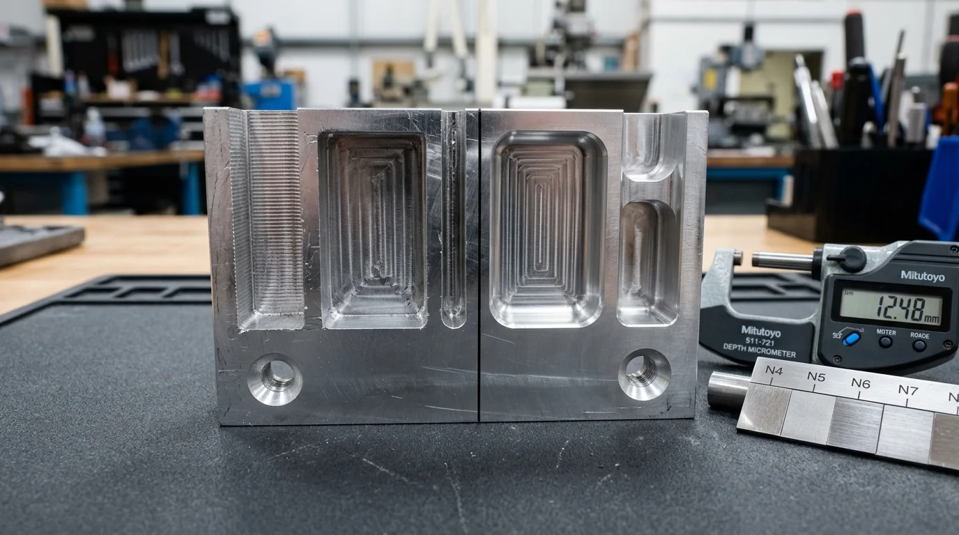
6. Undercuts, Complex Contours & Multi-Axis Geometry
Undercuts—geometric features that cannot be reached directly by a straight line-of-sight vertical cutting tool—demand specialized manufacturing planning.
Internal Undercut Geometry & Standard Cutters
Internal undercuts (such as retaining ring grooves, O-ring seal glands, and T-slots) must be machined using specialized tooling:
- Woodruff Keyway Cutters: Ideal for narrow O-ring grooves and circlip slots on internal bores or vertical side walls.
- T-Slot Cutters: Designed for milling under-flange horizontal slots.
- Dovetail Cutters: Ground to standardized angles, typically 45° or 60°. Avoid non-standard angles (such as 52° or 70°), which mandate expensive custom tool grinding.
Critical Clearance Rule: Always ensure adequate vertical clearance between the top of the undercut feature and any protruding upper flanges. Maintain at least 3.0 mm (0.120 in) of shank clearance to prevent the tool arbor from colliding with the workpiece.
Undercut & T-Slot Tool Clearance Design Rules
- Vertical Arbor Clearance: Maintain at least 3.0 mm (0.120 in) clearance between the top of the undercut cutter blade and the downward-facing upper flange face to avoid tool holder gouging.
- Radial Slot Depth Ratio: Keep undercut slot depth W ≤ 2 × cutter thickness T to prevent radial tool deflection.
- Bottom Floor Clearance: Provide minimum 1.5 mm clearance below the lower cutter edge when machining internal relief grooves.
When to Split Complex Billets into Assemblies
In advanced hardware design, engineers occasionally design monolithic, highly complex components featuring multi-sided undercuts, angled deep bores, and internal fluid channels.
While monolithic parts eliminate assembly fasteners, machining them often requires:
- Complex 5-axis simultaneous mill-turn operations.
- Massive raw material waste (hogging out a large billet to leave a thin spider-bracket).
- High scrap risk: a single tool failure on the 10th machining hour scraps the entire unit.
The DFM Alternative: Split complex monolithic designs into two or three simpler sub-components joined by:
- Precision dowel pins for sub-micron datum alignment.
- Standard socket head cap screws with O-ring face seals for fluid containment.
Splitting a complex part frequently reduces total manufacturing cost by 40\%–65\% by permitting high-speed 3-axis milling on simple stock billets.
For detailed tolerances on assembly alignment pins, review our CNC machining tolerances standard. To explore surface roughness requirements for O-ring sealing faces, consult our CNC surface finish guide.

7. Sourcing & DFM Engineering Review Protocols
Optimizing CAD models for CNC machinability is an iterative engineering process. Even experienced mechanical teams benefit from early collaboration with manufacturing machinists who inspect toolpaths, evaluate fixture kinematics, and identify cost-saving geometry before cutting metal.
At CNMP, design for manufacturability is not a passive checklist; it is an active engineering service integrated into our quoting and production workflow:
Free 24-Hour DFM Engineering Review
When you submit 3D CAD models (STEP, IGES) and 2D engineering drawings (PDF) for engineering evaluation, our applications engineering team performs a thorough DFM review within 24 hours:
- Cutter Accessibility Analysis: We verify that all internal pocket radii align with standard cutter tooling, highlighting areas where radiused transitions can eliminate costly EDM.
- Thin Wall & Aspect Ratio Verification: We flag slender ribs prone to vibration, suggesting gusset reinforcement or stepped wall geometry to ensure chatter-free surfaces.
- Tapping & Clearance Audit: We verify that blind tapped holes maintain adequate pilot drill relief and that thread engagement depths conform to the 1.5D–2D mechanical threshold.
- Tolerance-Cost Optimization: We cross-reference critical functional datums against standard ISO 2768-m specifications, identifying non-critical features where relaxing tolerances can slash machining time.
Proven Tier-1 Automotive Pedigree
Our precision DFM and production processes are validated by long-term manufacturing partnerships with global industry leaders. We manufacture precision air suspension valve blocks for Arnott and leak-free fluid transfer system fittings for Dytech, operating under stringent IATF 16949-aligned APQP and PPAP Level 3 documentation standards.
Rapid Prototyping to Low-Volume Scalability
Whether you are validating a single prototype or scaling to bridge production:
- Minimum Order Quantity (MOQ) = 1 Piece: Rapid functional prototyping with fast turnaround (3–5 business days).
- Bridge-to-Production Flexibility: Seamless scaling from 10 to 1,000+ pieces with dedicated modular fixturing and volume cost amortization.
- Precision Metrology: Certified inspection in our 20°C ± 0.5°C metrology laboratory utilizing Zeiss and Mitutoyo CMMs, achieving precision tolerances down to ± 0.005 mm (5 μm / ± 0.0002 in).
To initiate an engineering review or receive a comprehensive, DFM-optimized quotation on your project, explore our primary CNC milling services and CNC turning services capabilities, or connect directly with our engineering team by submitting your STEP files and 2D engineering drawings for a free DFM review.