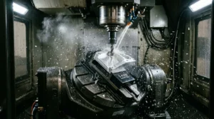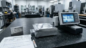
Understanding CNC machining cost is essential for mechanical engineers, hardware startup founders, and procurement managers balancing aggressive prototype schedules against production budgets. Machining is an inherently subtractive process where raw billet material, computer-aided manufacturing (CAM) programming, specialized carbide cutting tools, multi-axis machine run time, and post-process metrology all contribute to the final unit price.
At precision manufacturing facilities like CNMP, machining projects range from single-piece rapid functional prototypes to multi-thousand-part production runs. Evaluating quotes requires stripping away vague generalities and understanding the underlying manufacturing physics, machine shop hourly overheads, and setup amortization equations that govern custom part pricing.
At-a-Glance: CNC Machining Cost & Pricing Benchmarks (2026)
| Parameter | Industry Baseline Metric | Cost Impact / Range | |
|---|---|---|---|
| 3-Axis Milling Hourly Rate | China: \35–\50/hr \ | USA/EU: \75–\100/hr | Standard prismatic geometry, single-side setups |
| 5-Axis Machining Hourly Rate | China: \65–\95/hr \ | USA/EU: \125–\200+/hr | Complex 3D contours, done-in-one single setups |
| CNC Lathe / Turning Rate | China: \30–\45/hr \ | USA/EU: \65–\85/hr | Cylindrical symmetry, live tooling mill-turn |
| Typical Part Cost: Simple | \5 – \25 per part (Batch: 100–500 pcs) | 2D profiles, standard tolerances (±0.1 mm) | |
| Typical Part Cost: Medium | \25 – \100 per part (Batch: 100–500 pcs) | Multi-side features, pocketing, tight fits (±0.025 mm) | |
| Typical Part Cost: Complex | \100 – \500+ per part (Batch: 10–100 pcs) | Aerospace/fluid blocks, deep bores, 5-axis surfacing | |
| Fixed NRE Setup & CAM | \60 – \250 per production lot | Amortized across batch quantity (N) | |
| Achievable Tolerance Range | Standard: ±0.1 mm \ | Precision: down to ±0.005 mm | Tight tolerances increase machining & CMM inspection cost by 150%–300% |
The Anatomy of a CNC Machining Quote: 7 Cost Drivers
Every precision machining quote is calculated from a fundamental cost model balancing fixed non-recurring engineering (NRE) charges against variable per-unit manufacturing expenses:
Cunit(N) = Cmaterial + Cmachining + (Csetup / N) + Ctooling + Cfinishing + Cinspection + Clogistics
Where N represents the batch quantity. Understanding each component reveals where real cost reductions can be engineered before cutting metal.
1. Raw Material Stock and Swarf Yield Loss
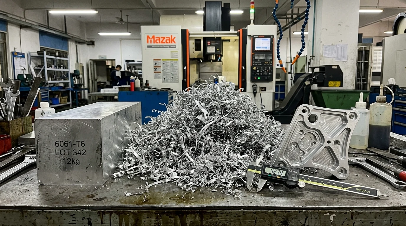
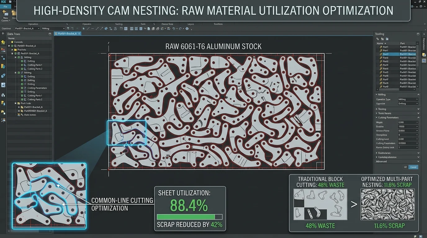
Raw material cost is governed not by the final part volume, but by the bounding box of the starting stock block or bar. Subtractive machining frequently removes 60% to 80% of the initial billet as swarf (metal chips).
- Stock Utilization Ratio: If a component measuring 95× 45× 22 mm is ordered, standard bar stock sizing requires an initial block of 100× 50× 25 mm. The removed material is sold as scrap at a fraction of virgin stock value.
- Alloy Surcharges: Commodity metals like 6061-T6 aluminum carry predictable baseline pricing (\3.50–\5.00/kg depending on market index), whereas aerospace titanium alloys (Ti-6Al-4V) or high-performance polymers (PEEK) command premiums exceeding \50–\150/kg.
2. Machine Time Cost (Hourly Rate × Cycle Time)
Machine time constitutes the largest direct variable cost. It is determined by the material removal rate (MRR), spindle speed (n), feed rate (v_f), and tool engagement paths:
MRR = v_c × f_z × a_p × a_e
Where v_c is cutting speed, f_z is feed per tooth, a_p is axial depth of cut, and a_e is radial width of cut. Harder alloys demand lower surface speeds and conservative depths of cut, directly multiplying spindle cycle time. Furthermore, machine classification dictates the operational hourly rate.
3. Non-Recurring Engineering (NRE) & Machine Setup
Before chips fly, considerable upfront engineering labor occurs:
- CAM Programming & Simulation: An applications engineer imports 3D CAD models into CAM software (e.g., Mastercam, PowerMill), generates optimized roughing and finishing toolpaths, checks for spindle housing collisions, and posts verified G-code.
- Workholding Setup & Fixturing: Mounting precision vises on machine beds, indicating datums with touch probes (Renishaw), machining custom aluminum soft jaws for contoured parts, and setting tool length offsets in the automatic tool changer (ATC).
- Setup represents a fixed expenditure (60–250 per setup). On a 1-piece prototype, this entire fee is absorbed by that single component. On 500 parts, it is diluted to pennies.
4. Perishable Tooling & Tool Wear Overhead
Carbide end mills, ball nose cutters, chamfer tools, and insert drills experience mechanical and thermal fatigue.
- Standard aluminum machining utilizes polished micro-grain carbide cutters with ZrN or TiB2 coatings, yielding long tool life and minimal edge wear.
- Machining abrasive or high-temperature alloys like 316 stainless steel, Inconel 718, or hardened tool steels (HRC 45+) accelerates edge chipping and flank wear. Shops factor a perishable tooling wear coefficient (typically 5%–15% of machine run cost) into production quotes.
- Non-standard geometries requiring custom form cutters, extra-long reach shank tools, or custom thread pitch taps add direct tooling surcharges.
5. Secondary Post-Processing & Surface Finishing
As-machined surfaces typically display microscopic cutter scallops (Ra 1.6–3.2 µm). Achieving functional protection or aesthetic appeal requires secondary batch processing:
- Bead Blasting: Glass bead blasting (#100–#150 mesh) removes light machining marks and unifies the visual sheen at modest cost (\1.00–\3.00/part).
- Anodizing (MIL-A-8625 Type II & Type III Hardcoat): Sulfuric acid bath treatment producing a controlled oxide layer. Type III hardcoat (25–50 µm thickness) provides extreme wear resistance and dielectric isolation, but requires precision dimensional pre-compensation.
- Passivation & Chemical Conversion: ASTM A967 chemical passivation removes free iron from stainless components; SurTec 650 or Alodine provides conductive corrosion resistance on aluminum.
- For complex assemblies, integrating multi-process post-treatments through integrated surface finishing services avoids fragmented vendor handoffs and compounding shipping charges.
6. Quality Control, Metrology & Documentation
Precision requires physical verification. A machine shop’s metrology commitment scales with part criticality:
- Standard Verification: Handheld micrometers, digital calipers, pin gauges, and optical comparators during in-process machining.
- CMM Verification: Automated Coordinate Measuring Machine (Zeiss, Mitutoyo) inspection verifying multi-axis geometric dimensioning and tolerancing (GD&T) features such as true position, concentricity, and profile of a surface.
- Document Packages: Automotive or aerospace contracts requiring First Article Inspection (FAI) reports under AS9102, 3.1 Material Mill Test Certificates, or PPAP Level 3 documentation require dedicated quality engineering hours, priced into the production lot.
7. Protective Packaging & International Freight
Finished parts must arrive without dented sealing faces, thread burrs, or atmospheric oxidation:
- Precision machined surfaces require individually partitioned trays, heat-sealed anti-corrosion VCI bags, or custom EPE foam cutouts.
- Logistics costs depend on weight and transit velocity: rapid functional validation favors 3–5 day express air courier (DHL, FedEx, UPS), while high-density production runs shift to palletized ocean freight.
CNC Machining Hourly Rates: Machine Types & Global Benchmarks
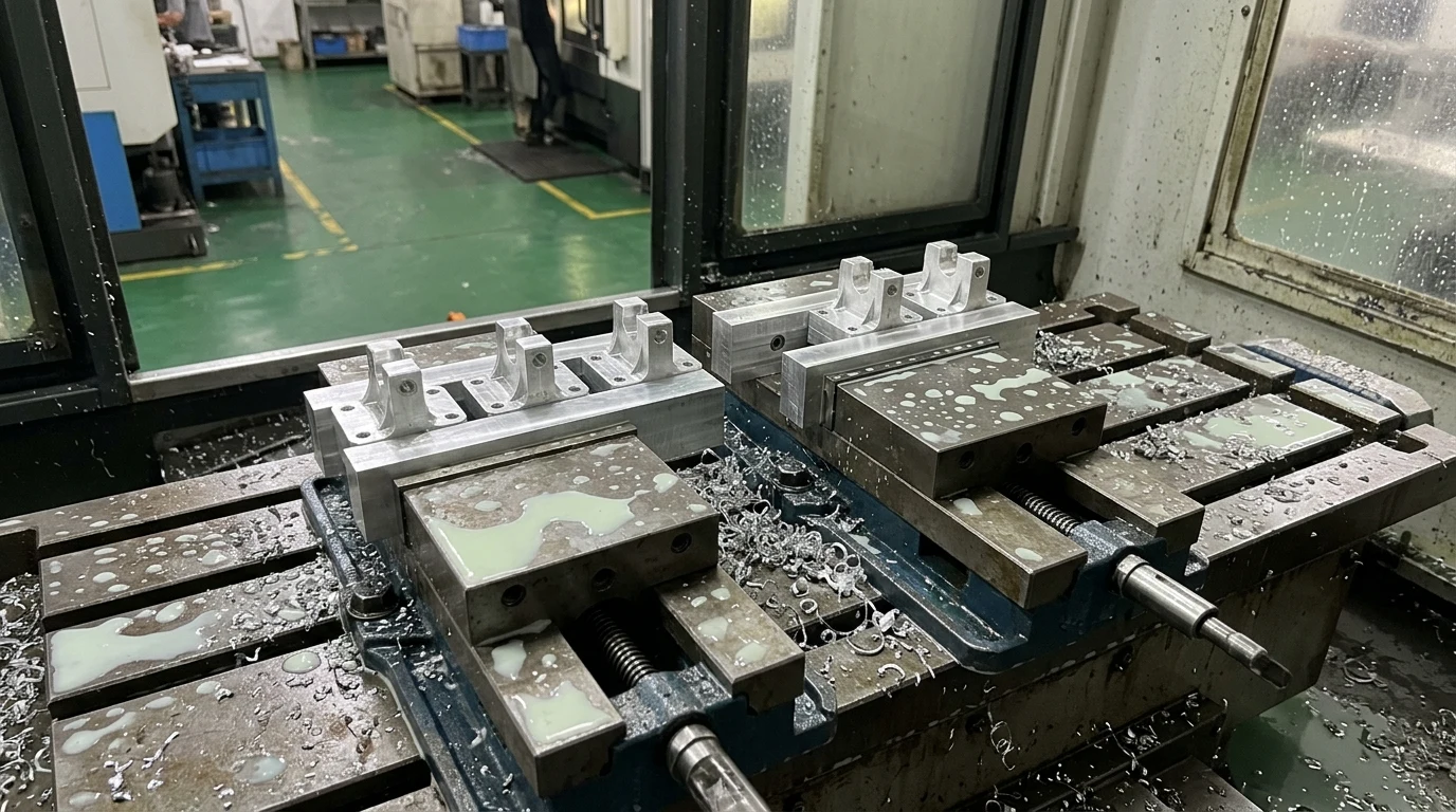
Machining costs vary widely depending on kinematic machine configuration, spindle power, and regional labor and energy overheads. The table below outlines realistic 2026 shop-floor hourly rates across primary machine categories:
| Machine Tool Classification | Typical Machine Envelope & Kinematics | China Hourly Rate (USD) | USA / EU Hourly Rate (USD) | Primary Application & Economics |
|---|---|---|---|---|
| 2-Axis CNC Lathe | 6″–10″ chuck, 2-axis turning | \30 – \45 / hr | \65 – \85 / hr | High-speed cylindrical shafts, pins, bushings, fasteners. Lowest setup and operating cost. |
| 3-Axis Vertical Mill (VMC) | 3-axis (X/Y/Z), 12,000 RPM spindle | \35 – \50 / hr | \75 – \100 / hr | Prismatic enclosures, mounting brackets, flat plates. Most common platform for general prototyping. |
| 4-Axis Mill (VMC + Rotary) | 3-axis + 4th-axis rotary indexer (A-axis) | \45 – \65 / hr | \85 – \120 / hr | Manifolds, radial cross-holes, continuous rotary helical milling without multiple manual flips. |
| Mill-Turn Multi-Tasking Center | Dual spindle, live tooling, Y-axis turret | \55 – \80 / hr | \110 – \160 / hr | Complex cylindrical components requiring cross-milling, flats, and off-axis tapping in one handling. |
| 5-Axis Simultaneous Machining | 5-axis trunnion table (X/Y/Z/A/C) | \65 – \95 / hr | \125 – \200+ / hr | Complex impellers, turbine blades, organic aerospace housings. Highest capital and programming cost. |
The 5-Axis Paradox: Why Higher Hourly Rates Can Lower Total Part Cost
Engineers frequently avoid 5-axis machining assuming it is automatically more expensive than 3-axis milling. However, evaluating total piece cost requires assessing fixture count and handling labor.
Consider an aluminum automotive sensor housing requiring precision bores and threaded ports on five distinct faces:
- The 3-Axis Approach: Requires 4 to 5 separate vise setups. An operator must manually unclamp, clean, reorient, and re-zero the part for each face. Each flip introduces operator handling labor (\20–\40/setup) and stacks datum alignment errors (± 0.025 mm variance). Total cycle plus setup time: 75 minutes across 5 operations.
- The 5-Axis Done-in-One Approach: The part is gripped once in a dovetail or self-centering 5-axis vise. The trunnion table articulates the workpiece continuously, presenting five faces to the cutter in a single uninterrupted cycle. Total cycle time drops to 22 minutes.
- Result: Despite a higher machine hourly rate (\80/hr vs \45/hr), the 5-axis solution reduces total machining cost by 40% while preserving true-position tolerances down to ± 0.005 mm. Comprehensive capabilities on high-end platforms are detailed in our custom CNC machining services overview.
Material Cost & Machinability Index: From Aluminum to Titanium
Material selection directly drives both raw stock expenditure and cutting cycle time. Machinability index represents the relative cutting speed an alloy tolerates compared to baseline free-machining steel (AISI 1212 = 100%) or Aluminum 6061-T6 (treated as 100% benchmark in non-ferrous manufacturing).
The engineering matrix below illustrates the trade-offs between raw material expense, cutting speed, and relative cycle time multiplier:
| Material Family & Specific Grade | Raw Material Cost Index | Machinability Rating (%) | Cycle Time Multiplier | Typical Machining Characteristics & Cost Implications |
|---|---|---|---|---|
| Aluminum 6061-T651 | Low (1.0x Baseline) | 100% (Baseline) | 1.0x | Free-cutting, excellent chip evacuation, high feed rates (3,000–8,000 mm/min). Lowest overall part cost. |
| Aluminum 7075-T6 | Moderate (1.3x) | 85% | 1.15x | Zinc-alloyed high strength. Slightly higher tool wear than 6061, excellent dimensional stability for structural parts. |
| Carbon Steel 1045 | Low-Mod (0.8x) | 65% | 1.45x | Inexpensive raw stock, but requires slower surface speeds (v_c = 150 m/min) and causes higher carbide insert wear. |
| Alloy Steel 4140 (Pre-hard) | Moderate (1.4x) | 55% | 1.80x | High tensile strength and fatigue resistance. Demands rigid setups, through-spindle high-pressure coolant, and coated tools. |
| Stainless Steel 304 | Mod-High (1.9x) | 45% | 2.20x | High work-hardening rate. Requires sharp positive-rake inserts, constant feed to prevent glazing, and frequent tool changes. |
| Stainless Steel 316L | High (2.3x) | 40% | 2.50x | Marine and medical grade with molybdenum. Extremely gummy chips, generates high cutting zone heat, slow feeds. |
| Brass C360 (Free-Cutting) | High (2.8x) | 160% | 0.65x | High raw material cost, but phenomenal machinability. Chips break effortlessly; cycle times are 35% faster than aluminum. |
| POM / Delrin (Acetal) | Moderate (1.2x) | 140% | 0.75x | Low tool wear and rapid cutting, but requires sharp tooling to prevent burrs. Sensitive to heat-induced dimensional creep. |
| PEEK (Polyetheretherketone) | Extreme (6.5x) | 70% | 1.60x | Ultra-performance polymer. Expensive raw material (\$120+/kg). Prone to internal stress cracking; requires pre-machining annealing. |
| Titanium Ti-6Al-4V (Grade 5) | Extreme (5.5x) | 25% | 4.20x | Low thermal conductivity traps heat at the tool edge. Requires low RPM (v_c = 40–60 m/min), high torque, and rigid setups. |
For deep property comparisons across aerospace, automotive, and medical alloys, refer to our comprehensive CNC machining materials guide.
Batch Scaling & Setup Amortization: Why 1 Piece Differs from 500 Pieces
The most common shock for hardware engineers transitioning from 3D printing to CNC machining is the radical price difference between ordering 1 prototype versus ordering 50 or 500 units.
The Mathematics of Amortization
CNC machining involves significant fixed setup overhead. Whether a shop produces 1 part or 1,000 parts, the following tasks must be completed:
- CAM toolpath programming and multi-axis collision simulation (2–4 hours).
- Machine table vise alignment and dial indicator tramming (0.5–1 hour).
- Tool loading into the ATC, height touch-off, and edge-finding work coordinate zeroing (0.5–1 hour).
- First Article dry run, cutting air, and running a test piece with 100% CMM verification (1 hour).
These fixed costs (C_{NRE}) sum to roughly \150–\300. As batch size (N) increases, this fixed charge is divided across more units according to the asymptotic curve:
Cunit(N) = Cvariable + (CNRE / N)
Real-World Engineering Case: 6061-T6 Fluid Manifold Block
To illustrate, consider an illustrative engineering example: a 6061-T6 aluminum fluid manifold block (120× 80× 45 mm) featuring multi-axis internal channels, O-ring sealing grooves (Ra 0.8 µm), threaded ports, and Type II black anodizing.
- Fixed NRE Setup: \160 total (\70 CAM programming + \$90 machine setup and first article verification).
- Variable Unit Cost: \14.20 (\4.50 raw material + \6.50 machine time [10 min @ \39/hr] + \$3.20 Type II anodizing).
| Production Batch Quantity (N) | Fixed Setup Fee per Part (C_{setup}/N) | Variable Cost per Part (C_{var}) | Total Finished Unit Price (C_{unit}) | Savings vs. Single-Piece Unit Price |
|---|---|---|---|---|
| 1 Piece (Rapid Prototype) | \$160.00 | \$14.20 | \$174.20 | 0.0% (Baseline) |
| 5 Pieces (Validation Batch) | \$32.00 | \$14.20 | \$46.20 | -73.5% |
| 25 Pieces (Pilot Build) | \$6.40 | \$13.50* | \$19.90 | -88.6% |
| 100 Pieces (Bridge Run) | \$1.60 | \$12.80* | \$14.40 | -91.7% |
| 500 Pieces (Production Batch) | \$0.32 | \$12.10* | \$12.42 | -92.9% |
\Variable costs decrease slightly at volume due to bulk raw stock discounts, multi-part vise fixturing, and reduced operator handling cycle times.*
For fast-turnaround validation before investing in volume runs, dedicated rapid CNC prototyping processes minimize non-essential documentation overhead to deliver functional units in 3 to 5 business days. When scaling beyond 10 units, transitioning into low-volume CNC machining maximizes setup amortization.
Tolerance Economics: The True Cost of Chasing Microns
A common mistake on engineering drawings is specifying blanket title-block tolerances of ± 0.025 mm (± 0.001 in) across every non-critical dimension. Machining physics dictates that tolerance tightening produces an exponential, rather than linear, cost curve:
| Tolerance Class | Standard Bilateral Spec | Relative Cost Multiplier | Shop Floor Manufacturing Impact |
|---|---|---|---|
| Standard Rough / Clearance | ±0.25 mm (±0.010 in) | 1.0× (Baseline) | Single roughing pass, standard tool feeds, standard caliper verification. |
| Commercial / ISO 2768-m | ±0.10 mm (±0.004 in) | 1.2× – 1.3× | Standard CNC machining, single finishing pass, manual micrometer check. |
| Precision Machining | ±0.025 mm (±0.001 in) | 1.7× – 2.0× | Dedicated finishing end mill, tool offset tuning, frequent in-process gauging. |
| High Precision / Tight Fit | ±0.010 mm (±0.0004 in) | 2.5× – 3.0× | Spring passes, pre-machining thermal stabilization, precision bore reaming. |
| Sub-Micron / Metrology Grade | ±0.005 mm (5 μm / ±0.0002 in) | 3.5× – 4.0×+ | 20°C climate-controlled shop, thermal compensation, 100% Zeiss CMM verification. |
Why Holding ±0.005 mm Multiplies Cost by 2.5x to 3.5x
- Machine Tool Deflection and Tool Wear: As carbide end mills cut, radial tool deflection occurs (y = (F × L3) / (3 × E × I)). To hold tight tolerances within ± 0.005 mm, an operator cannot rely on a single roughing and finishing pass. The machine must take multiple light “spring passes” at low chip loads to eliminate tool pressure deflection, doubling or tripling spindle cycle time.
- Thermal Expansion Drift: Aluminum expands at approximately 23 μm/m·°C. On a 100 mm aluminum feature, a shop temperature shift of just 3°C alters part dimensions by 0.007 mm—consuming the entire tolerance band! Holding microns requires temperature-controlled workshops stabilized at 20°C (68°F), thermal spindle compensation, and letting parts soak before final inspection.
- 100% CMM Metrology Verification: While standard tolerances are verified at the machine with digital micrometers in seconds, tight-tolerance bores and true-position features require mounting on a Zeiss Coordinate Measuring Machine inside an inspection lab, directly adding metrology billing hours. Verifiable inspection workflows are outlined in our precision quality assurance protocols.
The Golden DFM Rule: Specify standard ISO 2768-m tolerances (± 0.1 mm) for overall profiles, clearance pockets, and aesthetic faces. Restrict precision tolerances (± 0.01 mm or down to ± 0.005 mm) strictly to critical bearing press-fits, dowel locating pin centers, and hydraulic seal lands.
China vs. USA/EU CNC Machining Cost: The Landed Cost Reality
Sourcing precision CNC parts from overseas requires assessing total landed cost rather than nominal factory gate price:
C_{landed} = C_{exw} + C_{freight} + C_{tariffs} + C_{brokerage}
Where the Cost Discrepancy Comes From
- Skilled Machining Labor & Engineering Overhead: Machine operators, CAM programmers, and QA metrologists in North America and Western Europe command wages of \35–\60/hr, resulting in loaded machine shop rates of \75–\120/hr. In China, highly skilled machinists operate in dense industrial manufacturing ecosystems, yielding machine rates of \35–\55/hr for equivalent high-tier equipment (Haas, DMG MORI, Mazak).
- Raw Material & Finishing Ecosystem Density: In Chinese manufacturing clusters (e.g., Guangdong, Jiangsu), raw aluminum, stainless extrusions, heat treatment facilities, and anodizing lines reside within a 30-minute radius. This eliminates domestic logistics transit lag and lowers supply chain overhead.
Landed Cost Comparison: 100 Precision 6061-T6 Brackets
- USA Domestic Machine Shop Quote:
- Unit Machining Price: \$48.00 / pc
- Ground Freight: \80 total (\0.80 / pc)
- Total Landed Unit Cost: \$48.80 / pc
- Lead Time: 3–4 weeks
- China Precision CNC Manufacturer (Verified Tier-Supplier Baseline):
- Unit Machining Price (EXW): \$22.50 / pc
- Express Air Freight (DHL 4-day transit, \160 total): \1.60 / pc
- Customs Import Tariff (25% Section 301 / HS 8487.90): \$5.63 / pc
- Total Landed Unit Cost: \$29.73 / pc
- Lead Time: 2 weeks (machining) + 4 days (air transit) = 2.5 weeks
- Net Sourcing Outcome: 39.1% total cost savings delivered directly to the client’s door via express courier, even after paying air freight and customs duties.
10 Actionable DFM Rules to Slash CNC Machining Costs
Engineering drawings dictate manufacturing cost. Applying these ten Design for Manufacturability (DFM) rules directly shortens spindle cycle time and prevents custom tooling expenses:
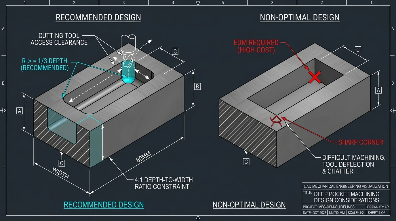
1. Increase Internal Corner Radii (R ≥ 1/3 × Depth)
Because rotating end mills are cylindrical, they cannot machine sharp internal 90° corners. If a pocket requires sharp vertical corners, it must be machined via slow, expensive wire electrical discharge machining (EDM).
- Specify an internal corner radius of at least 1/3 (ideally 1/2) of the pocket depth.
- This allows a standard, rigid tool to mill the pocket without requiring micro-diameter cutters operating at slow feed rates.
2. Limit Cavity Depth-to-Diameter Ratios (L/D ≤ 4)
Deep, narrow pockets demand long-reach cutting tools. As tool length (L) increases, cutter deflection (y) increases with the cube of length and inversely with the fourth power of diameter (y ∝ L3 / d4).
- Tools exceeding 4× D experience harmonic vibration and chatter, forcing operators to reduce spindle speeds by 60% and take microscopic depths of cut.
- Keep internal cavities shallower than 4× tool diameter to allow rigid, high-feed roughing.
3. Avoid Walls Thinner Than 0.8 mm (1.5 mm for Plastics)
Thin vertical walls deflect under lateral tool cutting pressures, resulting in chatter marks, dimensional tapering, and potential structural failure. Machining thin walls requires multi-stage, ultra-light passes that drastically extend cycle times. Maintain wall thicknesses above 0.8 mm for aluminum and steels, and above 1.5 mm for polymers.
4. Eliminate Unnecessary Undercuts and 3D Contours
Internal undercuts require specialized lollipop cutters, T-slot cutters, or multi-axis indexers. Where undercuts are required for snap-rings or O-rings, dimension them to match standard off-the-shelf grooving insert widths (1.1 mm, 1.3 mm, 1.85 mm, 2.15 mm). Avoid organic 3D aesthetic surfacing where flat chamfers accomplish the same clearance function.
5. Standardize Blind Hole Depths and Thread Sizes
Design tapped holes to standard UNC/UNF or metric sizes (e.g., M3, M4, M5, M6, M8). Never specify full-depth threads down to the absolute bottom of a blind hole; taps require clearance for chips and tap lead chamfers. Design blind tapped holes with a depth no greater than 2.5× to 3× the nominal screw diameter, with an unthreaded drill tip relief equal to at least 0.5× diameter.
6. Design for Minimum Workpiece Repositioning (Single-Setup DFM)
Every time a part is flipped to machine features on another face, labor costs increase and datum transfer tolerances compound. Try to align all pockets, chamfers, and threaded holes to a single primary orientation (+Z), or at most two opposing faces (+Z and -Z).
7. Avoid Blanket Tight Tolerances on Non-Critical Features
Reserve tight tolerances (± 0.01 mm / ± 0.0004 in) strictly for mating bores, bearing locations, and dowel pin alignment centers. Allow all other non-functional geometries to default to general machining tolerances (ISO 2768-m, approximately ± 0.1 mm to ± 0.2 mm).
8. Use Commercial Surface Roughness (Ra 3.2 µm Default)
Specifying an across-the-board mirror finish (Ra 0.4 µm / 16 µin) forces the machine to run fine finishing passes with minimal stepovers, adding hours of spindle run time. Specify Ra 3.2 µm (125 µin) as the default as-machined finish, and call out Ra 0.8 µm (32 µin) only on dynamic hydraulic sealing faces or sliding bearing contacts.
9. Replace Engraved 3D Text with Surface Laser Marking
Milling raised or recessed text into metal requires miniature engraving ball mills (0.5 mm diameter) spinning at 15,000+ RPM for dozens of minutes. Remove milled text from 3D CAD models entirely; specify surface laser marking instead, which applies permanent part numbers, logos, and date codes in seconds during post-processing.
10. Optimize Standard Stock Sizing (Near-Net-Shape Sizing)
If your finished component has an outer dimension of 50.8 mm (2.000 in), a machine shop must order 63.5 mm (2.5 in) raw bar stock and machine away 12.7 mm of material. If the design can be altered to 48 mm, the shop can utilize standard 50.8 mm stock, saving both raw material expense and roughing cycle time.
How to Get an Accurate, Binding CNC Machining Quote
Submitting incomplete or ambiguous drawing packages leads to padded quotes where suppliers add risk margins. To receive a competitive, binding quote within 24 hours, provide:
- Clean 3D CAD Files: Provide solid geometry in standard neutral interchange formats (STEP AP214/AP242 or IGES). Ensure solid bodies are manifold and free of corrupted surface geometry.
- Detailed 2D PDF Engineering Drawings: The 2D drawing is the legally binding specification. It must clearly call out:
- Material grade and temper condition (e.g., 6061-T651, 316L, POM-C).
- Critical tolerances and GD&T feature control frames (position, runout, flatness).
- Thread standards and class of fit (e.g., M6×1.0-6H, 1/4-20 UNC-2B).
- Surface roughness requirements (Ra values in micrometers or microinches).
- Secondary finishing specifications (e.g., MIL-A-8625 Type II Class 2 Black, glass bead blast #120).
- Quantity Breakdowns & Batch Forecasting: Always specify target volume tiers (e.g., 1 pc prototype, 25 pcs pilot, 200 pcs production). This enables programmers to quote appropriate multi-part production fixturing rather than defaulting to single-vise prototype setups.
- Target Delivery Timelines & Regulatory Requirements: State whether First Article Inspection (FAI) reports, 3.1 Material Mill Certs, or Certificate of Conformance (CoC) documents are required prior to shipment.
To review design files under non-disclosure protection and receive rapid DFM feedback, engineers can directly request a precision CNC machining quote with automated CAD upload and 24-hour engineering analysis.
Frequently Asked Questions (FAQ)
What is a typical CNC machining cost per hour in 2026?
Hourly machining rates depend on machine kinematic complexity and regional operating overhead. In China, standard 3-axis milling and CNC turning range from \30 to \50 per hour, while high-precision 5-axis machining ranges from \65 to \95 per hour. In North America and Western Europe, 3-axis rates range from \75 to \100 per hour, and 5-axis centers command \125 to \200+ per hour.
How does batch quantity affect the final price per part?
CNC machining incurs fixed non-recurring engineering (NRE) setup costs for CAM toolpath programming, machine fixture setup, and first-article CMM inspection (\150–\300 per lot). When ordering 1 prototype, this entire fee is absorbed by that single part. When ordering 100 or 500 parts, the setup cost is amortized across all units, typically reducing the per-part cost by 70% to 90%.
Why are aluminum parts generally the cheapest to CNC machine?
Aluminum (especially 6061-T6) combines modest raw material costs with superior machinability. It can be cut at high spindle speeds and aggressive feed rates with minimal cutting forces, resulting in rapid cycle times. Furthermore, aluminum causes very little tool wear on carbide end mills, eliminating frequent cutter replacements.
Are online automated CNC cost calculators accurate?
Automated instant web calculators provide reasonable ballpark estimates (± 25\%) for simple 2.5D prismatic shapes. However, they frequently fail to detect micro-features requiring custom tooling, deep internal bores prone to chatter, thin-wall vibration, complex multi-axis setups, or specific GD&T callouts. A manual DFM review by an experienced manufacturing applications engineer is always required for an exact, binding quote.
Does CNC machining have a minimum order quantity (MOQ)?
At modern precision CNC contract manufacturing facilities, there is strictly no minimum order quantity—the MOQ is 1 piece. Rapid prototyping orders allow hardware designers to validate physical form, fit, and mechanical function before committing to production tooling.
How much can smart DFM reduce my CNC machining quote?
Implementing proactive Design for Manufacturability (DFM) modifications—such as increasing internal corner radii (R ≥ 1/3 × Depth), keeping pocket depths under 4× D, eliminating unnecessary tight tolerances, and switching from milled text to laser marking—regularly slashes machining quotes by 30% to 50% without altering the part’s mechanical performance.