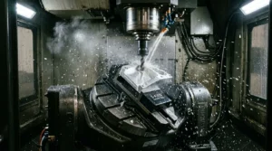
Machining a single custom metal or plastic component is structurally penalized by traditional manufacturing economics. In conventional machine shops, allocating a 3-axis or 5-axis machining center for an order of one piece triggers prohibitive setup charges—often exceeding $800 to $1,500—primarily because CAM programming, stock squaring, fixture alignment, and touch-probe calibration consume identical spindle-downtime whether running one unit or ten thousand. Consequently, procurement managers and hardware design engineers face an artificial barrier: prototype shops that refuse low-quantity work, or mass-production facilities that impose rigid minimum order quantities (MOQs).
CNMP eliminates this operational friction through dedicated rapid-response machining cells configured with standardized zero-point clamping systems, pre-calibrated tool magazines, and macro-driven toolpath generation. We accept one-piece CNC machining orders without arbitrary lot charges or minimum quantity thresholds. Every standalone component is machined directly from certified, stress-relieved wrought stock, maintaining dimensional tolerances down to ±0.005 mm (±0.0002 in) and verified on coordinate measuring machines (CMM) before air-express dispatch within 3 to 5 business days.
The Single-Part Dilemma: Why Most Machine Shops Say No
Procuring a single bespoke component presents unique commercial and operational challenges. Machine shops operate on spindle utilization metrics; non-cutting time directly degrades gross margin. Understanding this cost dynamic allows design engineers to structure their RFQs more effectively.
The Setup Cost Amortization Reality
Every CNC machining cycle consists of two distinct cost components: fixed Non-Recurring Engineering (NRE) setup expense and variable unit cutting cost.
Total Part Cost = (Setup Hours × Shop Hourly Rate + CAM Programming + Raw Stock) / Batch Quantity + Cycle Time × Machine Hourly Rate + Inspection & FinishingIn a production order of 5,000 pieces, an 8-hour engineering setup (including CAD modeling, fixture machining, G-code simulation, and tool zero-offset probing) priced at $100 per hour represents $800 in total setup cost. Amortized across the batch, the setup burden is merely $0.16 per component.
When the order quantity drops to exactly one piece (N = 1), that entire $800 setup expense rests upon a single component. Traditional job shops handle this by either quoting inflated “minimum lot charges” to guarantee profit or declining to bid entirely to protect machine capacity for high-volume automotive or aerospace contracts.
When 3D Printing Isn’t an Option: The Functional Imperative
Faced with steep single-piece machining costs, engineering teams frequently consider additive manufacturing as an alternative. While plastic SLS (Selective Laser Sintering) or metal DMLS (Direct Metal Laser Sintering) eliminate tooling setups, they introduce material and structural compromises unacceptable for end-use functional validation.
Layer-by-layer powder consolidation produces internal microscopic voids and anisotropic crystal grain structures. A 3D-printed aluminum (AlSi10Mg) component typically exhibits 15% to 25% lower fatigue resistance and elongation at break compared to wrought 6061-T6 bar stock.
Under dynamic mechanical shock, cyclic thermal stress, or pneumatic pressure above 6 bar (87 psi), additive parts risk micro-fracture and fluid leakage along inter-layer boundaries. When validating critical structural brackets, automotive suspension links, or pressurized fluid manifolds, testing requires the exact metallurgical properties and surface integrity of full-density billet material.
How CNMP Engineers Affordable One-Piece Machining
To make single-piece manufacturing economically viable without inflating lead times, CNMP restructured its facility operations, separating high-volume production lines from dedicated agile prototyping cells.
+-----------------------------------------------------------------------------------+
|                           CNMP Agile Prototyping Cell                             |
|                                                                                   |
|  +--------------------+   +--------------------+   +---------------------------+  |
|  | Standardized       |   | Pre-Calibrated     |   | Template-Driven           |  |
|  | Zero-Point Bases   |-->| 40-Tool Carousels  |-->| CAM Feature Macros        |  |
|  | (10-min changeover)|   | (Zero setup offset)|   | (Rapid toolpath compile)  |  |
|  +--------------------+   +--------------------+   +---------------------------+  |
|            |                                                     |                |
|            v                                                     v                |
|  +-----------------------------------------------------------------------------+  |
|  | Certified Wrought Stockyard (6061-T651, 7075, 316L, POM, 4140 in stock)    |  |
|  +-----------------------------------------------------------------------------+  |
+-----------------------------------------------------------------------------------+
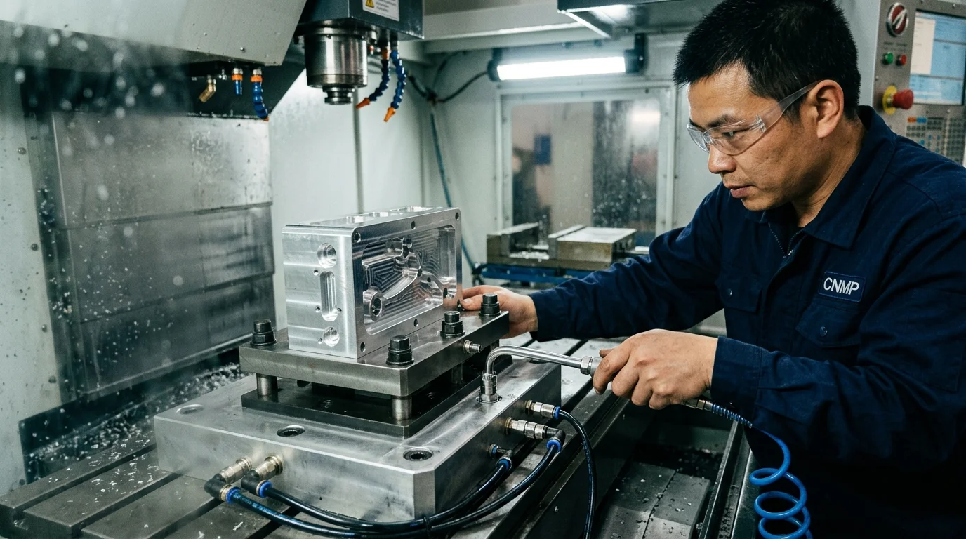
Standardized Zero-Point Clamping Systems
Conventional part fixturing requires indicating vise jaws with a dial test indicator, dialing in coordinate work offsets, and frequently machining custom aluminum soft jaws for contoured parts—a process consuming 1.5 to 3 hours.
CNMP equips its 3-axis, 4-axis, and 5-axis vertical machining centers with standardized pneumatic zero-point clamping receivers permanently anchored to the machine sub-plates. Precision ground master fixtures, self-centering vises, and pneumatic chucks dock into the receiver pins with repeatability under 0.002 mm (0.00008 in). Swapping setups between entirely different customer geometries requires under 10 minutes.
Pre-Configured Modular Tooling & Tool Libraries
Loading, setting, and measuring twenty individual cutting tools before a single cut creates massive unproductive downtime. In our prototyping cells:
- Machine tool carousels maintain a permanent library of 40 standardized cutters: solid-carbide high-performance end mills (1 mm to 16 mm diameter), ball nose cutters, thread mills, chamfer tools, and center-cutting drills.
- Tool geometry, extension lengths, corner radiuses, and runout values are pre-measured on optical offline tool presetters and stored in the CNC controller’s tool management database.
- Machine spindles switch from roughing aluminum to profile-finishing stainless steel without manual tool-loading cycles.
Template-Driven CAM Programming & Simulation
Our CAM programming team employs automated feature recognition (AFR) and parametric machining templates built in Mastercam and Siemens NX. Standard geometric elements—such as tapped hole patterns, bearing counterbores, O-ring sealing grooves, and open pocketing routines—are automatically populated with proven feeds, speeds, step-downs, and lead-in arcs.
Complete machine digital twins simulate cutting cycles and tool holder clearances in G-code verification software (VERICUT) before physical machining begins, eliminating dry runs and preventing collision risks on 1-off parts.
In-Stock Raw Material Stockyards
Material supply delays frequently stall single-part jobs. Sourcing a small cut piece of specialized alloy can incur vendor cutting surcharges and multi-day shipping delays. CNMP maintains an active on-site inventory of over 40 tons of certified wrought plates, round bars, and rectangular blocks, including 6061-T651, 7075-T6, 304, 316L, 4140, C360 brass, POM-C (Delrin), and virgin PEEK. Raw stock is sawn to blank dimensions within 30 minutes of order confirmation.
This operational framework forms the foundation of our rapid prototyping capabilities, providing engineers with a reliable route for urgent functional validation.
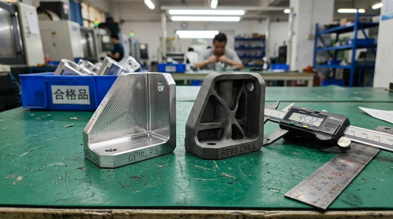
Single-Part CNC vs. Rapid 3D Printing: Engineering Decision Matrix
Selecting the appropriate prototyping modality requires balancing physical performance, dimensional rigor, geometric complexity, and unit economics.
| Engineering Parameter | One-Piece CNC Machining (CNMP) | Metal 3D Printing (DMLS / SLM) | Engineering Impact & Selection Rule |
|---|---|---|---|
| Material Density & Porosity | 100% Solid Wrought Structure (Zero micro-voids) | 99.0%–99.8% Density (Micro-porosity risk under pressure) | Critical for hydraulic blocks, vacuum chambers, and fluid connectors. Additive parts risk helium/air leakage above 5 bar. |
| Mechanical Strength & Isotropy | Fully Isotropic: Identical tensile and yield strength across X, Y, and Z axes | Anisotropic: Z-axis tensile and fatigue strength is 15%–30% lower than X-Y build plane | CNC is required for components subjected to multi-axial dynamic vibration, impact, or cyclic fatigue loading. |
| Linear Dimensional Tolerance | Down to ±0.005 mm (±0.0002 in) under thermal compensation | Typical as-built: ±0.1 mm to ±0.2 mm (Requires secondary machining for fits) | Press-fit bearing journals, dowel pin locations, and O-ring gland depths require CNC precision directly off the machine. |
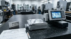
| Surface Finish (As-Processed) | Ra 0.8 µm – 1.6 µm (Turned / End-milled); down to Ra 0.2 µm with secondary polish | Ra 6.3 µm – 12.5 µm (Sintered powder texture; rough) | Dynamic sliding seals and rotary shafts will shred elastomer seals if processed with as-sintered additive textures. |
| Feature Geometries & Limitations | Limited by cutting tool reach, shank clearance, and corner radiuses | Capable of internal cooling channels, topological lattices, and undercut voids | Choose additive only for complex organic lattices impossible to machine via 5-axis toolpaths. |
| Thread Integrity & Fastener Strength | Directly tapped or thread-milled into base alloy with full shear engagement | Sintered threads require thread-chasing or wire-thread inserts (Helicoil) to prevent galling | Heavy-duty structural fasteners require machine-cut threads into homogeneous base metal. |
When physical properties must replicate production hardware precisely, single-part CNC machining is the definitive choice. Additive manufacturing remains advantageous primarily for topological weight-reduction structures or geometries with fully enclosed internal voids that rotating cutting tools cannot physically access.
Materials & Finishing Available for 1-Off Components
Single-part orders at CNMP receive access to identical engineering-grade materials and surface finishes as serial production runs.
+---------------------------------------------------------------------------------------+
|                         Available Material Spectrum for 1-Off Parts                   |
|                                                                                       |
|  [ Aluminum Alloys ]        [ Stainless & Alloy Steels ]     [ Engineering Polymers ] |
|  - 6061-T6 / T651 (Stressed) - 304 / 304L (General Fluid)    - POM-C / Delrin         |
|  - 7075-T6 (High-Strength)  - 316 / 316L (Marine / Medical)  - PEEK (High-Temp)       |
|  - 2024-T3 / 5052-H32       - 17-4 PH (Precipitation Hard)   - PTFE / Nylon PA66      |
|  - 6082-T6 (EU Structural)  - 4140 Chromoly / 1045 Carbon    - Polycarbonate / PMMA   |
+---------------------------------------------------------------------------------------+
Production-Grade Aerospace & Automotive Alloys
Selecting the correct material grade and temper condition prevents warping during machining and guarantees performance under operating stress:
- Aluminum 6061-T651: The standard benchmark for general structural framing, sensor brackets, and housings. The T651 temper indicates stress-relief stretching after solution heat treatment, drastically reducing residual stresses that cause thin-walled parts to curl or warp when internal material is excavated.
- Aluminum 7075-T6: Zinc-alloyed aerospace material delivering yield strength up to 505 MPa (comparable to structural carbon steel) at one-third the weight. Ideal for suspension control links, high-load gears, and robotic linkages. Compare specific alloy properties in our detailed 6061-T6 vs 7075-T6 aluminum guide.
- Stainless Steel 316L: Molybdenum-bearing austenitic grade offering superior resistance to chlorides and pitting. Essential for single-piece flow cells, pharmaceutical nozzles, and marine sensor enclosures.
- Alloy Steel 4140 (Pre-Hardened): Supplied at 28–32 HRC. Delivers outstanding fatigue strength, toughness, and wear resistance for drive shafts, spline couplings, and custom press-fit dies without requiring post-machining heat treatment distortion.
- Engineering Polymers (POM / Delrin & PEEK): Virgin, unreinforced POM-C provides excellent dimensional stability, low friction, and crisp machining characteristics for custom bushings and electrical insulating blocks. PEEK serves extreme environments requiring continuous operating temperatures up to 250°C and aggressive chemical resistance. Review our comprehensive CNC engineering materials guide for machinability indices and application matrices.
Secondary Surface Finishing for Single Parts
Single-piece prototypes frequently require surface treatments to simulate final product aesthetics, resist environmental corrosion, or establish electrical insulation. CNMP applies precision finishing to single units with strict dimensional compensation:
- Anodizing (Type II & Type III Hardcoat): Sulfuric acid anodizing provides cosmetic corrosion protection and color coding (clear, black, blue, gold). Type III Hardcoat deposits a dense 25–50 µm oxide layer with surface hardness exceeding 60 HRC. Because Hardcoat penetrates the surface by 50% and builds outward by 50%, our CAM engineers apply pre-machining dimensional compensation, undersizing outside diameters and oversizing tight bores by 12–25 µm to hit target print tolerances post-coat.
- Abrasive Bead Blasting: Utilizes #120 to #180 fine glass beads to remove directional tool cutter marks, producing a uniform, satin-matte finish (Ra 1.2–2.0 µm) that serves as an optimal substrate for anodizing or powder coating.
- Chemical Passivation: Citric or nitric acid immersion conforming to ASTM A967, stripping free iron from stainless steel surfaces to accelerate the formation of a protective chromium-oxide passive film.
- Direct Laser Marking: High-contrast fiber laser engraving of human-readable part numbers, serial codes, revision markers, or 2D Data Matrix barcodes directly onto metal surfaces. Explore all available treatments across our precision surface finishing services catalog.
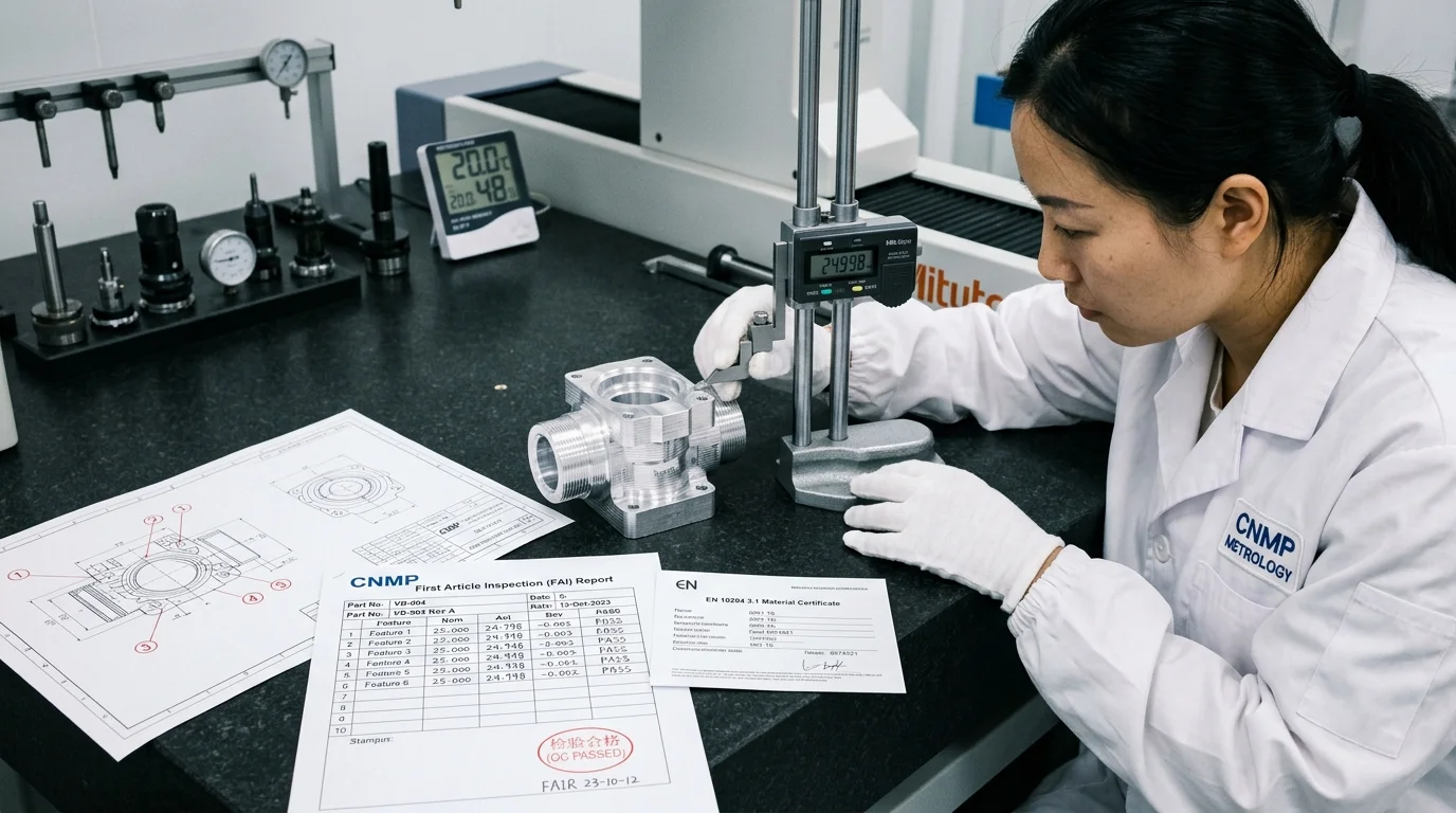
Quality Assurance for Quantity = 1: Zero-Defect Metrology
In mass production, quality control relies on Statistical Process Control (SPC) and Acceptance Quality Limit (AQL) sampling tables to identify defects across thousands of units.
For a one-piece order, statistical sampling is mathematically impossible. The sampling size is 100%, and the allowable defect margin is strictly zero. If a single dimension on a one-off component is machined 0.02 mm undersize, the entire delivery is scrap, threatening the client’s testing milestone.
+-----------------------------------------------------------------------------------+
|                        Single-Piece Quality Gate Workflow                         |
|                                                                                   |
|  [ In-Process Verification ]   -->   [ Thermal Stabilization ]                    |
|  - Renishaw infrared touch-probe     - 2-4 hour soak at 20°C ±1°C                 |
|  - In-situ bore & datum checks       - Thermal equilibrium restoration            |
|               |                                    |                              |
|               v                                    v                              |
|  [ Coordinate Metrology ]      -->   [ Comprehensive Documentation ]              |
|  - Zeiss Contura CMM                 - Full First Article Inspection (FAI)        |
|  - Mitutoyo optical projector        - 3.1 Mill Test Material Certificate         |
|  - Thread go/no-go gauges            - Certificate of Conformance (CoC)           |
+-----------------------------------------------------------------------------------+
In-Process Probing & Thermal Stabilization
Precision machining requires controlling physical variables before cutting tools contact material:
- Machine-Integrated Touch Probing: Spindles carry Renishaw high-accuracy optical probes to verify raw stock alignment, locate workpiece datum zero points, and measure critical bore diameters directly on the machine table between roughing and finishing passes.
- Thermal Stabilization: Metal machining generates significant friction and cutting heat. Precision components are stabilized in our temperature-controlled inspection laboratory at 20°C ±1°C (68°F) for 2 to 4 hours, allowing the thermal expansion coefficient of aluminum (23 µm/m/°C) to normalize before final metrology.
Metrology Inspection Protocol
Every single-piece component passes through comprehensive dimensional verification:
- Zeiss Contura CMM: Equipped with scanning probe heads, verifying 3D coordinate locations, profile tolerances, true position callouts, concentricity, and flatness down to 1.5 µm + L/350 accuracy.
- Optical Profile Projectors: High-magnification 2D optical comparator inspection for intricate groove profiles, thread pitches, and small corner chamfers.
- Certified Thread & Plug Gauging: Class 2B/3B internal threads and Class 2A/3A external threads verified using calibrated Go / No-Go plug and ring gauges.
- Surface Roughness Profilometry: Mitutoyo stylus contact profilometers tracing critical seal areas and bearing surfaces to confirm Ra, Rz, and Rmax roughness callouts.
Transfer of Automotive OEM Rigor (Arnott & Dytech Heritage)
CNMP applies the identical quality management disciplines developed for our tier-supplier automotive programs—including air suspension valve blocks for Arnott and leak-free fluid system fittings for Dytech—directly to single-part prototyping.
Automotive air suspension components operate under continuous 16-bar pneumatic pressures where a microscopic scratch on an O-ring gland bore causes system deflation. We inspect single-piece fluid blocks and sealing faces under 20x optical magnification for burr-free edges and zero surface porosity.
Every completed component ships with an individualized inspection package:
- Detailed First Article Inspection (FAI) Report documenting every 2D print dimension against actual CMM measurements.
- Material Test Report (EN 10204 3.1 Mill Certificate) certifying chemical composition and tensile properties from the original raw stock heat lot.
- Certificate of Conformance (CoC) verifying compliance with drawing specifications and applied surface finishing standards. Learn more about our shop floor standards in our precision CNC machining tolerances overview.
Real-World Engineering Scenarios
The following scenarios demonstrate how one-piece CNC machining resolves critical engineering roadblocks across industrial manufacturing and product development.
Illustrative Scenario A: Emergency Replacement for a Broken Assembly Line Manifold
- Background: A high-speed automotive packaging line in Germany suffered an unexpected catastrophic valve failure when an aluminum hydraulic distribution manifold cracked along an internal cross-drilled port. The original European equipment manufacturer quoted an 8-week replacement lead time, threatening hundreds of thousands of Euros in assembly line downtime.
- Component Specification: 1-piece custom hydraulic manifold, 180 mm × 140 mm × 85 mm. Material: 7075-T6 aluminum (required to withstand 210 bar dynamic fluid spikes). Tolerances: 5-axis angled intersecting oil ports with ±0.010 mm spool bore concentricity and Ra 0.4 µm seal seat finish.
- Manufacturing Execution: The client provided the original 3D CAD STEP file and 2D drawing. CNMP’s engineering team completed DFM review in 90 minutes, imported stock from our internal 7075-T6 billet rack, programmed multi-axis toolpaths, and machined the manifold in a single setup on a 5-axis machining center.
- Result: Following 100% CMM verification of all 14 valve cavity bores and pressure decay testing, the manifold was packaged and shipped via DHL Express on Day 3, clearing Frankfurt customs and arriving on the client’s plant floor on Day 5, restoring line operation 7 weeks ahead of OEM delivery schedules.
Illustrative Scenario B: Functional Testing of an EV Battery Cooling Connector
- Background: A tier-1 automotive hardware engineering team in North America was conducting thermal cycle validation on a next-generation electric vehicle (EV) battery cooling module. The design featured custom quick-disconnect coolant tube adapters with integrated dual O-ring retention glands. Previous attempts using metal DMLS 3D printing experienced coolant weepage at 4 bar pressure due to inter-layer powder porosity.
- Component Specification: 1-piece quick-disconnect fluid connector fitting. Material: 6061-T6 aluminum with Type II clear anodize. Tolerances: Dual O-ring seal diameter held to 14.500 mm +0.000 / -0.008 mm (±0.004 mm total band); surface roughness Ra ≤ 0.4 µm.
- Manufacturing Execution: CNMP turned the fitting on a CNC lathe equipped with live tooling. Using custom diamond-tipped profile inserts and in-machine Renishaw probing, the seal diameter was turned to nominal +0.002 mm, well within the 8-micron tolerance window. The part was clear-anodized with dimensional masking on the critical seal surfaces.
- Result: The single prototype successfully completed 1,000 hours of ethylene-glycol thermal shock testing between -40°C and +85°C at 10 bar continuous pressure with zero pressure decay, authorizing the design for subsequent bridge production.
Cost Breakdown & DFM Optimization Tips for One-Piece Parts
Understanding the cost mechanics of a 1-off machining quote enables engineering teams to modify non-critical geometry and significantly lower pricing without sacrificing functionality.
Anatomy of a 1-Off Machining Quote
Typical 1-Piece CNC Machining Cost Composition:
+-------------------------------------------------------------+
| CAM Programming & Toolpath Simulation           : 30% - 40% |
| Workholding Setup & Machine Indication          : 20% - 30% |
| Spindle Cutting Time (Cycle Time)               : 15% - 25% |
| Raw Material Billet & Sawing                    : 10% - 15% |
| CMM Inspection & FAI Documentation              : 10% - 15% |
+-------------------------------------------------------------+
Because CAM programming and setup labor represent up to 70% of the single-piece total, design modifications that streamline programming and toolpath execution directly yield cost reductions. Detailed cost calculations and price comparisons across processes are detailed in our CNC machining cost breakdown guide.
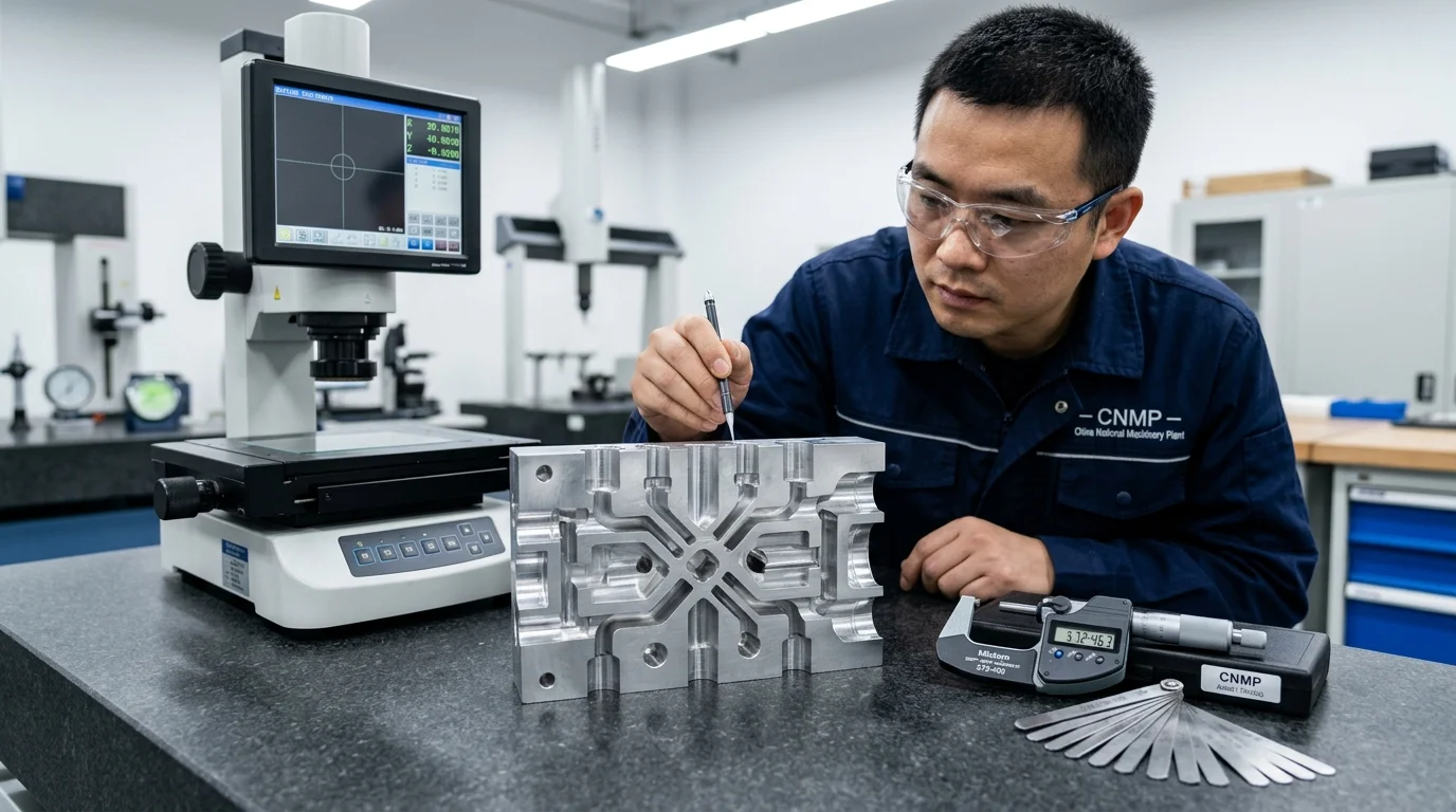
Five Actionable DFM Tips to Halve Your 1-Piece CNC Cost
+-----------------------------------------------------------------------------------+
|                        5 Key DFM Rules for 1-Piece Orders                         |
|                                                                                   |
|  1. Internal Radiuses       --> Use Corner R >= 1/3 Pocket Depth (Standard Mills) |
|  2. Pocket Aspect Ratio     --> Keep Depth-to-Width Ratio <= 4:1                  |
|  3. Standard Stock Sizing   --> Design Outer Dimensions 2mm Below Standard Plate  |
|  4. Selective Tolerancing   --> Restrict ±0.005mm to Mating Features Only         |
|  5. Dual-Format Prints      --> Submit 3D STEP + 2D PDF with GD&T Callouts        |
+-----------------------------------------------------------------------------------+- Avoid Sharp Internal Square Corners: Rotating end mills cannot cut sharp 90-degree internal vertical corners. Specifying zero-radius corners forces secondary wire EDM operations or small corner-picking tools that multiply machining time. Design internal corner radiuses at least 15% to 20% larger than standard cutter radiuses (e.g., specify an R3.5 mm corner rather than R3.0 mm so a standard 6 mm end mill can blend around the corner smoothly at high feed rates).
- Limit Pocket Depth-to-Width Ratios to 4:1: Deep, narrow pockets require extended-reach cutting tools that flex under cutting forces, causing chatter and dimensional taper. To prevent deflection, spindle feed rates must be throttled down by 75%. Maintaining pocket depth under 4 times the internal tool diameter ensures rigid, high-speed material removal.
- Design to Standard Stock Dimensions: When designing an aluminum enclosure measuring 52 mm × 102 mm × 27 mm, machining requires cutting down from a more expensive 60 mm thick billet. Sizing the part to 50 mm × 100 mm × 25 mm allows machining directly from standard pre-ground stock with minimal top and bottom face skimming.
- Apply Selective Tolerancing: Default drawing title blocks specifying “All tolerances ±0.01 mm unless noted” force machinists to run slow finishing passes and perform exhaustive CMM inspection on non-critical clearance walls and cosmetic edges. Assign tight tolerances (such as ±0.005 mm) strictly to bearing bores, pin locations, and sliding guides; leave non-critical exterior features to ISO 2768-m (±0.1 mm to ±0.2 mm).
- Provide Clean, Dual-Format Engineering Data: Submitting an ambiguous 3D model without a corresponding 2D PDF drawing forces engineering teams to clarify thread pitches, surface finishes, and tolerance fits, causing multiple back-and-forth email delays. Provide a clean 3D STEP file for CAM programming alongside a fully dimensioned 2D PDF drawing indicating critical GD&T datums.
From CAD to Delivery in 3–5 Days: The RFQ Process
CNMP provides a streamlined, transparent ordering workflow for single-piece custom machining orders, eliminating quotation delays and administrative overhead.
+---------------------------------------------------------------------------------------+
|                       5-Step Rapid 1-Piece Delivery Process                           |
|                                                                                       |
| [1. Upload CAD]  --> [2. 2h DFM & Quote] --> [3. Precision Machining]                 |
|   STEP/IGES + PDF      Fixed price & lead      3/4/5-Axis CNC                         |
|   Signed mutual NDA    Within 24 hours         Controlled 20°C                        |
|                               |                                                       |
|                               v                                                       |
|                      [4. 100% CMM QA]    --> [5. Air Express Dispatch]                |
|                        Zeiss/Mitutoyo CMM      DHL/FedEx Priority                     |
|                        FAI & Mill Cert         3-5 Day Global Delivery                |
+---------------------------------------------------------------------------------------+- Upload CAD & Engineering Package: Submit your 3D CAD model (
.STEP,.STP, or.IGES) and 2D drawing (.PDF) through our RFQ portal. Download our standard mutual Non-Disclosure Agreement (NDA) or upload your corporate agreement; your intellectual property remains fully protected under legal confidentiality protocols. - 2-Hour DFM Review & 24-Hour Firm Quotation: Our manufacturing applications engineers review your geometry for tool accessibility, deep-cavity constraints, and raw material availability. You receive an itemized, transparent quotation within 24 hours detailing machining hours, material allocation, surface finishing, and express freight charges.
- Precision Machining Execution: Upon order confirmation, pre-calibrated zero-point machining cells begin cutting chips immediately. Your component is machined on modern 3-axis, 4-axis, or 5-axis machining centers within our temperature-regulated production environment.
- 100% CMM Metrology Verification: The completed component undergoes rigorous cleaning, deburring, and thermal stabilization before entering our quality laboratory. Zeiss CMM operators measure all print dimensions, compiling an individualized First Article Inspection (FAI) report with material lot traceability.
- Protective Packaging & Global Air Dispatch: Components are vacuum-sealed, coated with rust-preventative oil where applicable, encased in custom high-density shock-absorbing foam, and dispatched via DHL Express, FedEx Priority, or UPS Worldwide with full tracking. Standard delivery to North America and Europe requires 3 to 5 business days.
When your functional test succeeds and your design is ready for pilot production, transition smoothly into our low volume CNC machining service to capture setup cost amortization across batches of 10 to 1,000 pieces.
Frequently Asked Questions (FAQ)
Do you truly accept orders for exactly 1 piece, or is there a hidden minimum lot charge?
CNMP accepts orders for exactly 1 piece with zero minimum order quantities (MOQ). We do not impose artificial $500 or $1,000 minimum lot charges. Our automated zero-point clamping fixtures and standardized tool libraries allow us to calculate prices purely based on actual CAM programming time, machine spindle cycle time, raw stock volume, and finishing requirements.
What is the realistic turnaround time for a single custom CNC part?
Standard delivery time for a single CNC machined part in aluminum, mild steel, or engineering plastic is 3 to 5 business days for machining and inspection, plus 3 to 4 business days for international express transit via DHL or FedEx Priority to the US, Canada, or Europe. Projects requiring complex secondary surface treatments (such as Type III Hardcoat anodizing or electroless nickel plating) typically require an additional 2 to 3 business days.
Can you achieve tolerances down to ±0.005 mm on a 1-off part without running setup trial scrap?
Yes. Achieving tight tolerances down to ±0.005 mm (±0.0002 in) on a single piece without trial iterations requires rigorous in-process verification. We use machine-integrated Renishaw infrared touch-probes to locate exact workpiece zero datums and measure preliminary finishing passes directly in the machine spindle, applying automated tool-offset adjustments before taking the final micron-level finish cut. Completed parts are verified on Zeiss coordinate measuring machines in a temperature-controlled metrology laboratory.
What drawing files and specifications do I need to submit for a fast 1-piece quote?
The optimal submission package includes a 3D CAD model in .STEP, .STP, or .IGES format for CAM toolpath calculation, accompanied by a 2D engineering drawing in .PDF format. The 2D drawing should clearly define critical dimensional tolerances, geometric dimensioning and tolerancing (GD&T) callouts, thread thread-class specifications, surface roughness targets (Ra), and secondary finishing requirements. If your part has no tight fits, a 3D STEP file with non-critical dimensions governed by ISO 2768-m is fully sufficient.
Once my single-piece prototype is validated, how do we transition to batch production?
Because your 1-piece prototype was programmed, simulated, and cut using production-grade CAM routines and standard tooling libraries, scaling up is a direct transition from prototype to production. Your validated CAM files, toolpaths, and inspection routines are permanently archived in our ERP system. When you authorize pilot runs of 25, 100, or 500 units, the initial CAM programming expense drops away entirely, and setup costs amortize across the batch, reducing your per-part price by 60% to 80%.
Do you supply material certificates and CMM inspection reports for 1-piece orders?
Yes. Every single-piece order is treated with identical metrological discipline. Upon request, we provide a complete documentation package consisting of an individualized First Article Inspection (FAI) report with CMM coordinate data, raw material chemical and mechanical test certificates (EN 10204 3.1 Mill Certs), and a formal Certificate of Conformance (CoC).
Fast-Track Your 1-Piece Machining Order
Transitioning a critical design from CAD to a physical, production-grade component should not involve weeks of administrative friction or vendor hesitation. CNMP operates dedicated prototyping cells designed to process single-piece orders with the same metrological discipline applied to our tier-supplier automotive programs for Arnott and Dytech.
How to Initiate Your Project:
- Prepare Your Engineering Package: Export your 3D geometry in standardized format (
.STEPor.IGES) alongside a dimensioned 2D drawing (.PDF) indicating critical tolerances, thread callouts, surface roughness specifications, and secondary finishing requirements. - Execute Mutual Protection: Download and sign our mutual Non-Disclosure Agreement (NDA), or submit your company’s standard agreement. All proprietary IP remains strictly confidential.
- Receive Application-Engineering Feedback: Our manufacturing engineers evaluate your geometry, providing automated and manual Design for Manufacturability (DFM) feedback within 2 hours, highlighting potential tool clearance or wall-thickness constraints.
- Lock In Fixed Pricing & Delivery: Receive a guaranteed 24-hour quotation detailing material lot traceability, spindle cycle time, Zeiss CMM inspection parameters, and international express freight options.