In subtractive manufacturing and mechanical design, choosing between 3-axis and 5-axis CNC machining represents one of the most critical cost and quality decisions an engineering team will face. While 3-axis vertical machining centers (VMCs) remain the foundational workhorses of precision machine shops worldwide, the emergence of multi-axis machining has transformed the production of complex components.
However, selecting 5-axis machining is not merely a matter of part complexity. Sourcing multi-axis machining centers introduces a distinct set of physical and economic trade-offs: higher machine hourly rates ($100–$150/hr vs. $45–$65/hr for 3-axis), specialized CAM programming overhead, and complex kinematic error budgets. Conversely, forcing a multi-sided or deep-cavity component onto a 3-axis mill inflates non-recurring engineering (NRE) costs for custom fixtures, requires repeated manual part repositioning, multiplies dimensional tolerance stackup errors, and forces tools to operate with excessive cantilever overhang.
Understanding when to leverage 5-axis CNC machining services versus standard 3-axis milling requires evaluating tool deflection physics, machine kinematics (specifically positional 3+2 indexing versus continuous simultaneous interpolation), volumetric accuracy, and total batch manufacturing economics.
At-a-Glance: 3-Axis vs. 3+2 Positional vs. Continuous 5-Axis Machining
| Architectural Parameter | Standard 3-Axis Milling | 3+2 Positional (5-Axis Indexing) | Continuous Simultaneous 5-Axis |
|---|---|---|---|
| Active Kinematic Axes | 3 Linear (X, Y, Z) simultaneously | 3 Linear (X, Y, Z) cutting while 2 Rotary (A/C or B/C) are locked | All 5 Axes (X, Y, Z, A, C or B) interpolate simultaneously |
| Table / Spindle Rotary Clamping | None (Fixed vertical or horizontal spindle) | Mechanical / Hydraulic disc brakes locked (2,000–4,000 Nm torque) | Continuously driven via direct-drive torque motors |
| Typical Cutting Dynamic Rigidity | Very High (Direct transmission to cast-iron bed) | High to Very High (Solid locked trunnion platter) | Moderate to High (Limited by harmonic drive stiffness) |
| Setup Count for 5-Sided Prismatic Part | 3 to 6 separate setups / vise reclampings | 1 single setup (“Done-in-One”) | 1 single setup (“Done-in-One”) |
| Tool Overhang Length (L/d Ratio) | Long (L/d ≥ 5–8), prone to cantilever chatter | Short & Stubby (L/d ≤ 2–3), tilted into cavity | Shortest possible (L/d ≤ 2), dynamically tilted |
| Geometric Tolerance & Datum Stackup | Stackup error (±0.03–0.06 mm) across flips | Unified Datum Reference Frame (≤ ±0.010 mm) | Unified Datum Reference Frame (≤ ±0.010 mm) |
| Typical Machine Hourly Rate (China / Global) | $45 – $65 / hour | $75 – $95 / hour | $110 – $150 / hour |
| Optimal Production Geometry | Flat plates, 2.5D brackets, shallow cavities | Prismatic manifolds, valve bodies with angled cross-holes | Aerodynamic impellers, turbine blisks, organic medical implants |
Core Kinematics: How 3-Axis, 3+2 Positional, and 5-Axis Simultaneous Differ
Every CNC milling machine operates within a standard Cartesian coordinate system. Understanding the mechanical distinction between positional indexing and simultaneous contouring is essential for optimizing toolpaths and avoiding unnecessary machine costs.
1. Standard 3-Axis Machining Kinematics
In a standard 3-axis CNC vertical milling center (VMC), the cutting tool moves along three linear orthogonal axes:
- X-Axis: Longitudinal movement (left-to-right table travel).
- Y-Axis: Transverse movement (front-to-back saddle travel).
- Z-Axis: Vertical movement (up-and-down spindle travel).
Because the cutting tool remains permanently oriented parallel to the Z-axis, subtractive cutting is strictly limited to features directly accessible from the top face. Any undercut, lateral cross-hole, or angled chamfer requires stopping the machine, un-clamping the component, flipping it manually into a secondary fixture, and re-probing the part coordinate zero via standard precision CNC milling services.
2. The 3+2 Positional Misconception (5-Axis Indexing)
A widespread industry misconception is that all 5-axis machining involves continuous simultaneous motion. In real-world precision manufacturing, approximately 75% to 85% of multi-axis production is executed via 3+2 positional machining (also known as 5-sided machining).
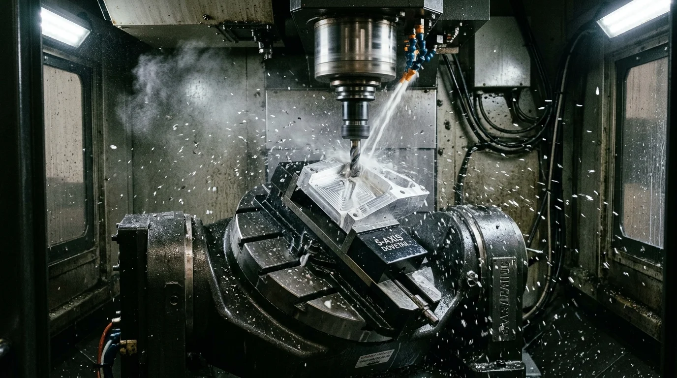
- The Mechanical Mechanism: The machine utilizes its two rotary axes (A and C, or B and C) exclusively to orient the workpiece at a compound angle. Once the target angle is reached, heavy-duty pneumatic or hydraulic disc brakes lock the rotary axes solidly, exerting clamping holding torques between 2,000 Nm and 4,500 Nm.
- The Cutting Action: Once locked, the machine cuts using standard 3-axis linear interpolation (X, Y, Z).
- The Engineering Benefit: Because the rotary axes are mechanically clamped, the machine achieves immense structural rigidity. This allows machinists to execute heavy-feed roughing passes with large-diameter face mills and high-feed indexable cutters—cutting forces that would induce severe vibration on an unclamped simultaneous rotary table.
3. Continuous Simultaneous 5-Axis Machining
In true continuous simultaneous 5-axis machining, all three linear axes (X, Y, Z) and two rotary axes (A, B, or C) interpolate concurrently in real-time under high-speed CNC control.
- Dynamic Spindle Vectoring: The CNC controller continuously calculates the spatial vector of the cutting tool relative to the surface normal of the CAD model. The tool can tilt dynamically to maintain an optimal lead and lag angle against complex, continuous organic surfaces.
- Controller Algorithms (RTCP / TCPM): Continuous motion requires high-end numerical processing such as Heidenhain TNC7 (TCPM), Siemens 840D/Sinumerik ONE (TRAORI), or Fanuc 31i-B5 (High-Speed RTCP). These algorithms ensure that the physical contact point between the cutting tool tip and workpiece remains mathematically synchronized regardless of how the machine table tilts or rotates.
- Essential Applications: Continuous simultaneous motion is physically mandatory for parts where tool vectoring cannot be stopped—such as closed-shroud aerospace impellers, turbine blisks, deep-draw mold cavities with variable draft angles, and organic orthopedic knee/hip implants.
The Physics of Tool Deflection: Why 5-Axis Eliminates Chatter and Taper
The single greatest physical advantage of 5-axis machining over 3-axis is not geometric freedom—it is cutting tool rigidity. In deep-pocket subtractive machining, tool cantilever deflection dictates surface quality, dimensional taper, and tool wear rates.
The Cantilever Beam Deflection Formula
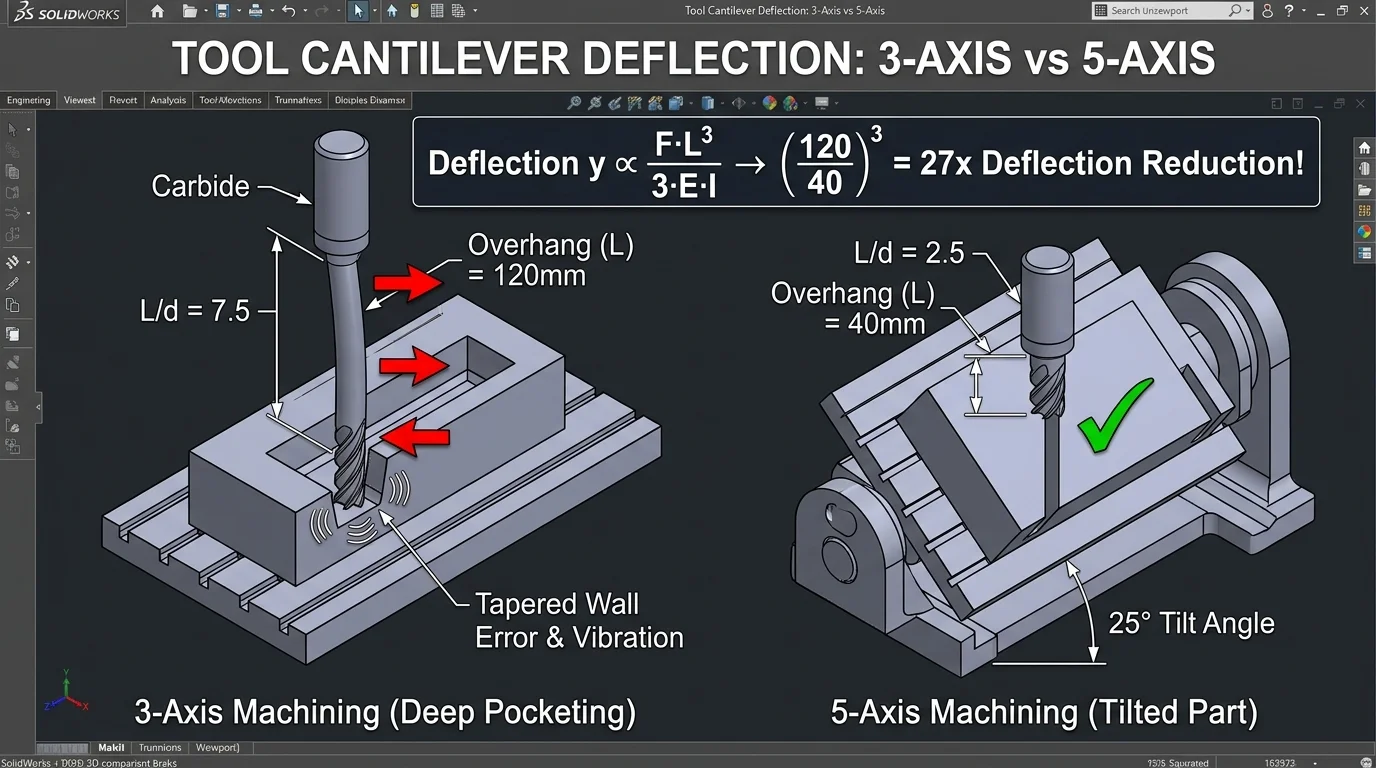
An end mill clamped in a toolholder acts mechanically as a cantilever beam subjected to a point load at its tip. According to classical Euler-Bernoulli beam mechanics, the static deflection (y) of an end mill subjected to radial cutting force (F) is:
y = (F × L³) / (3 × E × I) ≈ (64 × F × L³) / (3 × π × E × d⁴) ∝ (F × L³) / d⁴
- Where y is the tool tip deflection (µm).
- F is the radial cutting force perpendicular to the tool axis (N).
- L is the cantilever stick-out length from the toolholder collet (mm).
- E is the Young’s modulus of the cutting tool substrate (carbide ≈ 600 GPa, steel ≈ 210 GPa).
- d is the effective core diameter of the end mill (mm).
The Exponential Cubic (L³) Penalty in 3-Axis Deep Cavities
The mathematical relationship reveals that tool deflection scales with the cube of the overhang length (L³):
- If tool stick-out length doubles (2× L), deflection increases by 2³ = 8×.
- If tool stick-out triples (3× L), deflection increases by 3³ = 27×!
Consider a practical engineering scenario: milling an internal pocket 100 mm deep in a 6061-T6 aluminum aerospace electronics enclosure using a Ø16 mm solid carbide end mill.
- The 3-Axis Approach: Because the spindle cannot tilt, the end mill must extend straight down into the cavity with an overhang length of L = 120 mm (L/d = 7.5). Under a moderate radial cutting load of 250 N, the tool tip deflects by over 0.065 mm (65 µm). The vertical wall develops an unacceptable taper of 0.065 mm, exceeding typical drawing tolerances (±0.025 mm). The operator must reduce feed rates by 70%, take multiple spring passes, or drop radial width of cut (ae) to a fraction of a millimeter. This inflates cycle time and induces harmonic chatter, resulting in poor surface finish (Ra > 3.2 µm).
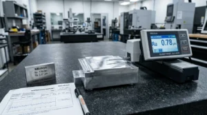
- The 5-Axis Approach: By tilting the workpiece or spindle head by 20° to 30°, the machine eliminates clearance interference between the bulky toolholder spindle face and the part perimeter. The machinist can utilize a stubby, ultra-rigid end mill with only L = 40 mm (L/d = 2.5) stick-out. Deflection drops from (120)³ / (40)³ = 27×. The stubby tool deflects by less than 0.0025 mm (2.5 µm) under identical chip loads! This unlocks zero wall taper, 300% higher metal removal rates (MRR), eliminated chatter, and superior as-machined finishes achieving Ra 0.8 µm directly from the cutter per our CNC surface finish guide.
Machine Architectures: Trunnion (Table-Table) vs. Swivel-Head (Head-Table / Head-Head)
Not all 5-axis machines behave identically. Multi-axis CNC milling centers are built on three primary kinematic arrangements, each suited to specific component sizes and payload masses.
1. Trunnion Style (Table-Table Architecture)
Linear axes (X, Y, Z) operate via the spindle column and bed. The two rotary axes are mounted directly in the workpiece table: an A-axis (tilting cradle) and a C-axis (rotary platter), typical of Hermle C-Series, Haas UMC-750, and DMG MORI DMU 50 machines.
- Advantages: The spindle assembly remains strictly vertical, ensuring maximum structural mass and dynamic cutting stiffness. Better undercut access: The tilting table can articulate +30° to -120°, providing expansive angular reach. Exceptional volumetric accuracy for small-to-medium parts (< 500 mm footprint).
- Limitations: Workpiece weight is strictly limited (typically < 300–500 kg). Heavy billets induce tilting platter deflection and overload rotary worm gears. Part rotation moves the center of gravity dynamically, requiring advanced controller inertia compensation.
2. Swivel-Head Style (Head-Table or Head-Head Architecture)
In Head-Table machines, the spindle head contains one rotary tilting axis (B or A), while the machine table contains the other rotary axis (C). In Head-Head machines, both rotary axes are housed inside the articulating spindle head (common on large gantry aerospace mills).
- Advantages: The table remains completely stationary or purely rotational on the horizontal plane. It accommodates extreme payloads (> 1,500 to 5,000 kg+) without risking table deflection, making it ideal for massive aerospace structural frames and heavy molds.
- Limitations: The tilting spindle head requires an articulated swivel housing, which possesses lower static torsional stiffness than a fixed vertical ram. The bulky envelope of the tilting spindle head can collide with high vise jaws or deep cavity walls.
Master Architecture Trade-Off Matrix: Trunnion vs. Swivel-Head vs. 3-Axis
| Machine Characteristic | Standard 3-Axis VMC | 5-Axis Trunnion (Table-Table) | 5-Axis Swivel-Head (Head-Table / Head-Head) |
|---|---|---|---|
| Spindle Torsional Stiffness | Highest (Fixed monolithic vertical casting) | High (Monolithic vertical spindle) | Moderate (Articulating pivot joints reduce stiffness) |
| Maximum Workpiece Mass | High (500 to 2,000 kg) | Moderate (< 250 to 500 kg) | Very High (1,500 to 10,000 kg+) |
| Working Envelope / Part Size | Small to Very Large (2,000 mm+ beds) | Compact to Mid-size (< Ø600 mm) | Large to Massive (1,000 to 6,000 mm) |
| Undercut & Cavity Access | Zero (Top-down only) | Superior (+30° to -120° platter tilt) | Good (Limited by spindle knuckle radius) |
| Thermal Growth Sensitivity | Low (Linear Z thermal drift only) | Moderate (Rotary platter center calibration) | High (Pivot point thermal drift requires chillers) |
| Best-Fit Part Types | Simple brackets, base plates, 2.5D tooling | Precision valve bodies, impellers, medical parts | Aerospace bulkheads, engine blocks, large molds |
Accuracy & Tolerance Realities: 3-Axis Datum Stackup vs. 5-Axis RTCP Error Budget
A common myth among procurement teams is that 5-axis machines are inherently more accurate than 3-axis machines. In metrology reality, the truth depends entirely on setup datum stackup versus kinematic volumetric error budgets.
The 3-Axis “Datum Relocation Stackup Trap”
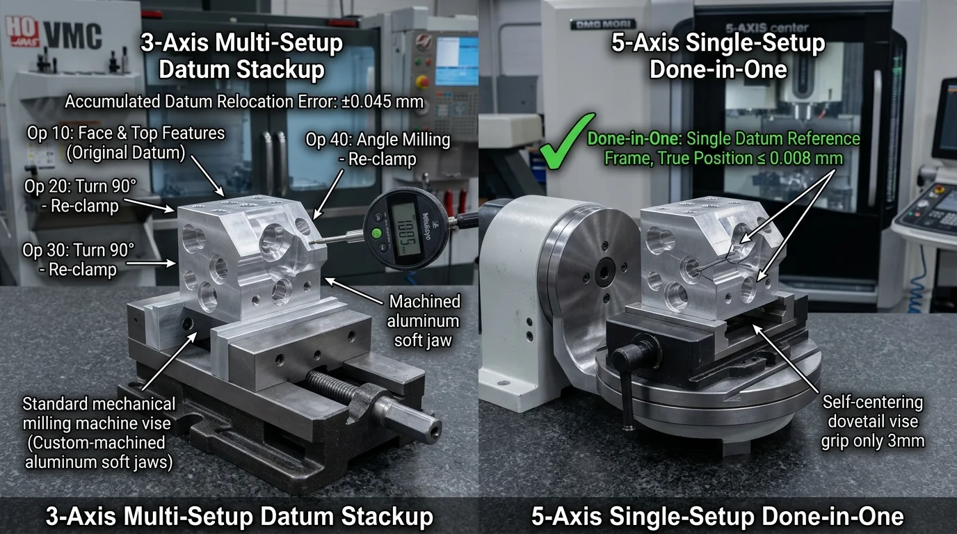
When manufacturing a multi-sided hydraulic valve block or fluid manifold on a 3-axis mill, the part must be flipped and re-clamped across multiple operations (Op 10 to Op 40). Every single vise re-clamping introduces cumulative physical errors:
- Vise Clamping Distortion: Clamping pressure deforms the part elastically (5–15 µm).
- Chip Smeared Seating: A microscopic swarf particle (20 µm) trapped between the vise jaw and raw stock tilts the entire workpiece coordinate system.
- Probing Inconsistency: Re-finding part edges with edge finders or touch probes introduces operator/machine variance (±0.010 mm).
By the fourth operation, cumulative positional error stackup frequently exceeds ±0.040 to ±0.060 mm. Critical geometric tolerances—such as perpendicularity between cross-holes and true position (⌖) between opposing fluid galleries—are blown out, resulting in rejected parts per our CNC machining tolerances guide.
The 5-Axis Single-Setup Advantage (“Done-in-One”)
In 5-axis machining, the raw stock is clamped via a high-grip 5-axis dovetail vise or self-centering micro-serrated chuck, gripping only the bottom 3 mm of sacrificial stock. All 5 exposed faces are machined in a single clamping. Datums A, B, and C are probed once using an automated Renishaw wireless touch probe. Because the part is never un-clamped, relational features across orthogonal and compound angles maintain true position tolerances of ≤ ±0.010 mm (0.0004 in).
The Real 5-Axis Kinematic Error Reality
However, 5-axis machining introduces its own unique kinematic errors that design engineers must understand:
- Rotary Axis Centerline Drift: A minute angular alignment error of 0.005° (18 arcseconds) in the rotary C-axis translates into a positional deviation of
Δx = R × sin(θ) = 200 mm × sin(0.005°) ≈ 0.017 mm (17 µm)at an outer radius of 200 mm! - Thermal Kinematics: As direct-drive torque motors and spindle bearings heat up during serial production, machine kinematic pivot points drift.
- The Solution: Advanced multi-axis production facilities utilize automated volumetric kinematic calibration routines (such as Renishaw AxiSet Check-Up or Heidenhain KinematicsOpt) using high-precision ceramic calibration spheres to re-calibrate machine pivot points every 8 hours, guaranteeing true single-digit micron capability.
Economic Analysis: When Does 5-Axis Actually Save Money?
Procurement directors often look exclusively at machine hourly rates: Standard 3-Axis VMC ($45–$65/hr) versus High-Performance 5-Axis Center ($100–$140/hr). At first glance, 5-axis appears twice as expensive. However, evaluating part cost solely by machine hourly rates is a fundamental procurement error. Part cost is governed by Total Manufacturing Cost, which incorporates fixture tooling NRE, setup labor, handling cycle times, and scrap rates.
Concrete Cost Case Study: Hydraulic Flow Manifold (Batch of 25 Pieces)
Consider an aluminum 6061-T6 fluid manifold requiring precision features on 5 sides: 4 angled cross-drilled fluid ports, 12 tapped bolt holes, internal O-ring cavities, and an H7 spool bore:
| Cost Category | 3-Axis Production Workflow | 5-Axis (3+2 Positional) Workflow | Financial Delta & Analysis |
|---|---|---|---|
| Number of Setups Required | 5 discrete setups (Op 10 to Op 50) | 1 single setup (Done-in-One) | 5-axis eliminates 4 setup cycles |
| Fixture NRE & Material | $1,800 (5 sets of custom aluminum soft jaws & alignment pins) | $150 (Standard off-the-shelf 5-axis dovetail vise stock) | $1,650 upfront fixture savings on 5-axis |
| Setup & Programming Labor | 5 setups × 1.5 hrs × $60/hr = $450 setup labor + $450 CAM | 1 setup × 2.0 hrs × $60/hr = $120 setup labor + $600 CAM | $180 lower net setup labor on 5-axis |
| Per-Part Machining Cycle Time | 52 minutes (cumulative across 5 handling stops) | 35 minutes (continuous 3+2 cutting with short, aggressive tools) | 17 minutes saved per part (32.7% faster runtime) |
| Machine Runtime Cost (25 pcs) | (52 min / 60) × 25 × $55/hr = $1,192 | (35 min / 60) × 25 × $125/hr = $1,823 | 3-axis runtime is $631 cheaper |
| Total Production Batch Cost | $4,612 | $3,043 | 5-Axis is $1,569 Cheaper (34% Net Savings!) |
| Final Unit Cost Per Part | $184.48 / piece | $121.72 / piece | $62.76 per piece lower cost on 5-axis |
The Procurement Takeaway: For low-to-mid volume batches (1 to 100 pieces), 5-axis machining is frequently cheaper in total invoice cost than 3-axis machining. The elimination of expensive custom fixturing and repeated setup labor dramatically offsets the higher machine hourly rate. Detailed pricing formulas can be explored in our CNC machining cost breakdown.
Step-by-Step Engineering Decision Tree: 3-Axis vs. 3+2 vs. Continuous 5-Axis
When reviewing 2D drawings and 3D CAD models, follow this 5-point engineering algorithm to determine the optimal manufacturing process:
- Rule 1: The Orthogonal Plane Rule (≤ 2 Faces): If all part features (pockets, holes, slots) reside on one or two opposing planar surfaces (e.g., standard mounting plates, simple brackets, heat sinks), choose 3-axis machining. 5-axis provides zero economic or geometric benefit.
- Rule 2: The Multi-Sided Prismatic Rule (3 to 5 Faces): If the component requires machining on 3, 4, or 5 faces (e.g., electronic chassis, gearboxes, fluid valve blocks with cross-ports), choose 3+2 positional 5-axis. Done-in-one clamping eliminates fixture costs, cuts lead times from weeks to days, and guarantees sub-0.010mm true position.
- Rule 3: The Deep Cavity Aspect Ratio Rule (L/d > 4): If the part contains internal pockets where cavity depth exceeds 4 times the corner fillet diameter (L/d > 4), standard 3-axis milling will encounter severe tool chatter and wall taper. Choose 3+2 positional machining. Tilting the part 20° allows stubby tools to reach deep corners with zero deflection.
- Rule 4: The Continuous Organic Geometry Rule: If the part features continuous compound-curved aerodynamic or hydrodynamic surfaces where tool contact angle must smoothly vary—such as centrifugal impellers, turbine blades, propeller screws, or orthopedic prosthetics—continuous simultaneous 5-axis is mandatory.
- Rule 5: The Production Volume vs. Fixture Amortization Rule: For prototypes and low volume (1 to 50 pcs), 5-axis is almost always superior because it eliminates the multi-thousand-dollar NRE expense of designing and building custom 3-axis soft jaws. For mass production (> 5,000 pcs/year), dedicated high-speed 3-axis or 4-axis horizontal mills with tombstone fixtures and automated pallet changers may become cheaper as tooling amortizes to pennies per part.
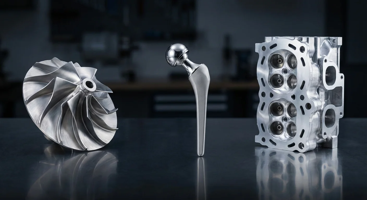
CNMP Multi-Axis Precision Machining Capabilities
Bridging multi-axis engineering theory with real-world manufacturing execution requires precision multi-axis machining centers, advanced CAM software, and rigorous metrology verification.
At advanced manufacturing centers like CNMP, our temperature-controlled production facility integrates high-precision 5-axis machining centers (including Hermle and DMG MORI simultaneous units) alongside high-speed 3-axis and 4-axis production cells. Every multi-axis setup is calibrated using Renishaw AxiSet kinematic check routines and verified on Zeiss Coordinate Measuring Machines (CMM) inside our 20.0°C metrology laboratory.
Whether you require rapid functional prototypes from MOQ = 1 piece delivered in 3 to 5 business days via our CNC prototyping services or bridge production of complex aerospace and automotive manifolds, our application engineers provide full Design for Manufacturability (DFM) reviews to determine the most cost-effective machining path.
To optimize your component geometry or receive a comprehensive 3-axis vs. 5-axis cost comparison, explore our full 5-axis CNC machining services or request a precision CNC machining quote with your 3D STEP models and 2D prints today.
Frequently Asked Questions (FAQ)
What is the difference between 3-axis, 4-axis, and 5-axis CNC machining?
A 3-axis CNC machine cuts along three linear perpendicular axes (X, Y, Z). A 4-axis machine adds one rotational axis (typically the A-axis rotating around X or B-axis rotating around Y), ideal for cylindrical turned parts or cutting features around a shaft. A 5-axis machine incorporates three linear axes and two rotational axes simultaneously (either A/C or B/C), allowing the cutting tool to approach the workpiece from any compound spatial angle.
Is 3+2 axis machining the same as simultaneous 5-axis machining?
No. In 3+2 positional machining (5-axis indexing), the machine uses its two rotary axes only to tilt and orient the part to a fixed compound angle, after which mechanical or hydraulic disc brakes lock the rotary axes solidly during standard 3-axis cutting. In simultaneous 5-axis machining, all 5 axes interpolate concurrently in real-time, allowing the cutter to continuously adjust its tilt angle while moving along complex 3D organic surfaces.
Why is 5-axis CNC machining more expensive per hour than 3-axis?
5-axis machining centers require significantly higher capital investment ($250,000 to $600,000+ compared to $60,000 to $120,000 for standard 3-axis VMCs). Additionally, 5-axis machining demands high-end CAM software licenses (such as Hypermill, Mastercam 5-Axis, or PowerMill), collision simulation software (Vericut), advanced kinematic calibration protocols, and highly trained CNC programmers.
How does 5-axis machining improve dimensional tolerances and GD&T?
By utilizing single-setup (“Done-in-One”) fixturing, 5-axis machining eliminates the need to un-clamp, flip, and re-clamp workpieces across multiple operations. This eliminates cumulative datum relocation stackup errors (which typically add ±0.03 to ±0.05 mm on 3-axis mills) and ensures that all multi-sided features share a single, unified Datum Reference Frame with true position tolerances held within ±0.010 mm.
Can a 3-axis machine manufacture parts with angled or undercut features?
A standard 3-axis vertical machine cannot directly cut undercuts or angled features in a single setup because the tool spindle remains strictly vertical. To produce angled holes or undercut profiles on a 3-axis mill, the shop must build custom sine plates, angled fixtures, or rotary indexers, requiring multiple manual setups that inflate labor costs and introduce tolerance stackup risks.
When is 3-axis machining preferred over 5-axis?
3-axis machining is strongly preferred for flat plates, 2.5D brackets, planar tooling, and simple prismatic housings where all critical features reside on one or two opposing faces. In these applications, 3-axis machining delivers lower machine hourly rates ($45–$65/hr) with zero programming overhead. Additionally, for massive production volumes (> 10,000 parts), multi-station 3-axis or 4-axis horizontal mills with tombstone fixtures are often more economical than 5-axis machines.