Lathe vs Mill: What is the Difference Between Milling and Turning?
By The CNMP Expert Team
If you are new to CNC manufacturing, the terminology can be confusing. Two machines dominate the shop floor: the Lathe and the Mill.
Knowing the difference between them is the first step to designing affordable parts. Choosing the wrong machine for your geometry can double your manufacturing costs.
The Short Answer:
- Lathe (Turning): Used for Round parts. The part spins; the tool is stationary.
- Mill (Milling): Used for Square/Flat parts. The tool spins; the part is stationary.
But what if you need a square hole in a round shaft? Or a complex curve on a bolt? This is where CNC milling and turning converge.
In this guide, we dive deep into the Lathe vs Mill comparison, explaining the mechanics of the process, and introducing the hybrid machine that does both: the Mill-Turn Center.
The Core Concept: Spin the Part or Spin the Tool?
To understand Lathe vs Mill, you only need to remember one rule: Rotation.
1. The CNC Mill (Milling)
- Physics: The workpiece is clamped firmly to a table (using a vise). A rotating cutting tool (End Mill or Drill) moves around the stationary part to cut away material.
- Geometry: Creates Prismatic shapes. Think of blocks, plates, brackets, and complex 3D surfaces.
- Axes: Moves in 3 axes (X, Y, Z).
- Analogy: Like a sculptor using a power chisel on a block of stone.
2. The CNC Lathe (Turning)
- Physics: The workpiece (usually a round bar) is clamped in a spinning chuck. A stationary cutting tool (Insert) moves against the rapidly spinning metal to “peel” it away.
- Geometry: Creates Cylindrical shapes. Think of shafts, pins, bushings, and threads.
- Axes: Moves in 2 axes (X, Z).
- Analogy: Like a potter shaping clay on a spinning wheel.

Lathe vs Mill: The Comparison Matrix
Quick reference for engineers.
This table highlights the key difference between milling and turning:
| Feature | CNC Mill | CNC Lathe |
| Primary Motion | Tool Rotates | Part Rotates |
| Best For | Flat, Square, Complex 3D | Round, Cylindrical, Tapered |
| Tooling | End Mills, Face Mills, Drills | Inserts, Boring Bars |
| Cutting Action | Interrupted (Tool teeth hit/exit) | Continuous (Tool stays in contact) |
| Cost Efficiency | Lower for round parts | High for round parts |
| Surface Finish | Swirling Arcs (Tool marks) | Parallel Lines (Smooth) |
Integrating CNC Milling and Turning (Case Studies)
When designing a part, you must decide which process leads.
Scenario A: The Drive Shaft
- Design: A long metal rod with threads on the end.
- Verdict: Lathe.
- Why: A lathe can cut the cylinder and the threads in seconds. A mill would have to slowly trace circles around the part, which is slow and inaccurate.
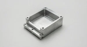
Scenario B: The Electronics Enclosure
- Design: A rectangular aluminum box with pockets for a PCB.
- Verdict: Mill.
- Why: You cannot spin a rectangular box effectively. A mill can carve out the pockets and drill the mounting holes easily.
Scenario C: The “Hybrid” Part
- Design: A round shaft with a flat keyway milled on the side.
- Verdict: Mill-Turn (Live Tooling).
The Game Changer: Mill-Turn Capability
Why choose one when you can have both?
In the traditional Lathe vs Mill debate, you had to pick one. If you needed that “Hybrid Part” (Scenario C) mentioned above, you used to have to:
- Turn the shaft on a Lathe.
- Move it to a Mill to cut the flat keyway.
This is obsolete.
At CNMP, we offer advanced CNC milling and turning in a single setup using Live Tooling Lathes.
- How it works: The lathe spindle stops spinning and acts like a rotary table. A small motorized milling head (Live Tool) inside the lathe turret spins up to drill holes, mill flats, or cut shapes—all while the part is still in the lathe chuck.
- The Benefit: We go from raw bar stock to finished part in one operation. This ensures perfect concentricity and lowers your cost.

Surface Finish: Visual Differences
How to identify the process by looking at the part.
- Turned Finish (Lathe):
- Looks like fine parallel lines wrapped around the cylinder.
- Generally smoother (Ra 0.8 – 1.6μm).
- Ideal for sealing surfaces (O-rings).
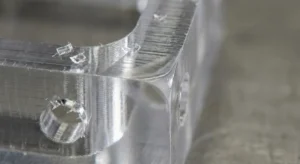
- Milled Finish (Mill):
- Looks like swirling arcs or “scallops.”
- Rougher (Ra 1.6 – 3.2μm) unless a “Face Mill” is used.
- Often requires Bead Blasting to hide these marks.
Summary: How to Order
You don’t need to be a machinist to make the right choice. Just follow this logic:
- Is it Round? -> It goes on a Lathe.
- Is it Square/Blocky? -> It goes on a Mill.
- Is it Complex? -> We use a Mill-Turn center.
Still unsure?
Don’t worry about selecting the machine. Just upload your CAD file. Our engineers will analyze the geometry and select the most efficient Lathe vs Mill process for your project.
Get your Instant Quote today and let CNMP handle the machining strategy.